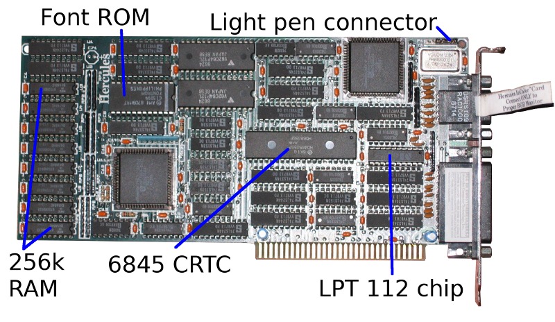
Hercules InColor Card: Notes
The InColor Card was Hercules Graphics' attempt to compete with the EGA; like the EGA, it outputs a 16-colour 720×350 display to an EGA monitor. The difference is that unlike the EGA, it's backwards compatible with programs written for the original Hercules Graphics Card and Hercules Graphics Card Plus, rather than those written for the CGA and MDA.
It is not to be confused with the Hercules Color Card, a CGA clone designed to be installed alongside a monochrome (or InColor) Hercules card.
- Hardware requirements
- The hardware
- Memory Map
- Register I/O
- Memory Access
- Character attributes
- Recommended CRTC values
- The printer port
Hardware requirements
The InColor is an 8-bit ISA card containing the display controller and a printer port. When present in a computer, it requires the following system resources:
- 4k-64k of RAM at address 0B0000h.
- I/O addresses 03B0h-03BFh.
- The printer port uses IRQ7.
The hardware
Output is from a DE9 socket. The pinout of this socket is:
- Ground
- Secondary red
- Primary red
- Primary green
- Primary blue
- Secondary green
- Secondary blue
- Horizontal sync
- -Vertical sync
The font rom is marked AMI C15994 FONTROM (the same ROM is used on the Hercules Graphics Card Plus). As on the original IBM MDA, this is a 9264 rather than a 2764, so it can't be read in a standard EPROM programmer. The memory layout isn't the same as on the MDA, so you can't swap the chip with one from an MDA and expect it to make sense. Both ROMs are divided into four 2k blocks; on the MDA, the font is in blocks 0 and 1, but here it is in blocks 1 and 3.
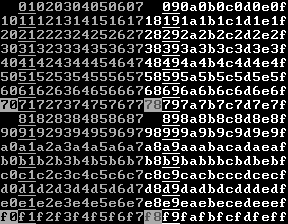
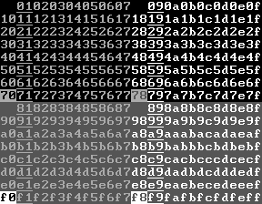
The card uses the 14-pixel font in the ROM:
![[14-pixel Hercules Plus font]](Images/hercplus.png)
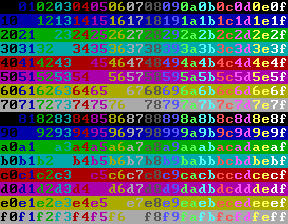
The ROM also contains two 8-pixel fonts (in blocks 0 and 2) which do not appear to be used.
![[8-pixel Hercules Plus fonts]](Images/hercplus8.png)
Memory Map
On power-up, the InColor card behaves like an MDA, producing an 80×25 text screen in white on black. Each character is 9 pixels wide and 14 high, giving a 720×350 pixel resolution. Although the characters are 9 pixels wide, the bitmaps in the ROM (or the RAM) only cover the first 8. For characters 0C0h-0DFh, the ninth pixel column is a duplicate of the eighth; for others, it's blank.
In text mode, the usual MDA-esque scheme is used, with two bytes of RAM for each character. The first byte is the character code, and the second gives the attribute.
On startup, the character attribute scheme behaves like an MDA:
- Bits 2-0: 1 for underline.
- Bit 3: High intensity (foreground colour is 15, not 7).
- Bit 7: If blinking is enabled: Blink. Else bright background (colour is 8 rather than 0).
with eight exceptions:
- Attributes 00h, 08h, 80h and 88h display as black space.
- Attribute 70h displays as black on grey (colour 0 on colour 7).
- Attribute 78h displays as grey on grey (colour 8 on colour 7).
- Attribute F0h displays as a blinking version of 70h (if blinking is enabled); as black on white (colour 0 on colour 15) otherwise.
- Attribute F8h displays as a blinking version of 78h (if blinking is enabled); as grey on white (colour 8 on colour 15) otherwise.
The card can also use a CGA-like attribute scheme, in which bits 3-0 give the foreground colour, 6-4 the background colour, and bit 7 is set to blink. If blinking is disabled, bits 7-4 give the background colour.
| Blink enabled | |
|---|---|
| MDA-like attributes | CGA-like attributes |
 |
 |
| Blink disabled | |
| MDA-like attributes | CGA-like attributes |
 |
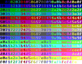 |
Register I/O
03B4h: CRTC address register.
Write a CRTC register number (0 to 1Ch) to this port to select the CRTC register that will appear at port 03B5h. Registers 0-11h are standard 6845 registers and are described on the 6845 datasheet.
Registers 14h-1Ch are used to control the InColor card's additional features, and are described below.On the MDA, the CRTC address and data register are partially decoded, so that any even-numbered address between 03B0h and 03B7h will get you the CRTC address register, and any odd-numbered address gets you the data register. I don't know whether this holds for the InColor card.
This is a write-only register.
03B5h: CRTC register read/write.
This gives access to the selected CRTC data register. Most CRTC registers are write only; some are read/write or read-only.
03B8h: Mode Control Register
This is a write-only register. The following bits are used:
Bit 7: Graphics page to display
If bit 7 is 1, the graphics page at 0B8000h is displayed. Otherwise, the page at 0B0000h is displayed.
Bit 5: 1 to enable blinking, 0 to disable it.
If bit 5 is 1, characters with attribute bit 7 set will blink. If not, they will have high intensity background.
Bit 3: 1 to enable video output, 0 to disable it.
If bit 3 is 0, screen output will not be shown. The usual use of this is if you're reprogramming the CRTC registers; disable video output beforehand and re-enable it after.
Bit 1: 1 for graphics mode, 0 for text.
When the card is switched between text and graphics modes, the 6845 must be reprogrammed with suitable parameters for the new mode.
03B9h: Set light pen flip-flop
Any write to this port sets the flip-flop.
03BAh: Status Register
This is a read-only register.
- Bit 7: 0 if vertical sync active, 1 if inactive.
- Bits 6-4: Card ID (101b = 5 for InColor).
- Bit 3: Video. This is 1 if a pixel is being drawn on the screen at this moment.
- Bit 1: Light pen flip-flop.
- Bit 0: Retrace. This is 1 if the horizontal retrace is active.
03BBh: Reset light pen flip-flop
Any write to this port resets the flip-flop.
03BFh: Graphics mode enable
This is a write-only register.
- Bit 1: Set to page in the upper 32k of memory at 0B8000h, clear to page it out.
- Bit 0: Set to allow graphics mode, clear to disallow it. Also enables access to memory from B1000h to B7FFFh.
Additional CRTC registers
The additional CRTC registers are:
Register 14h: xMode
This is a write-only register, initialised to 0 on reset. The following bits are used:
Bit 0: 0 to use ROM font, 1 to use RAM font.
If the RAM font is selected, character bitmaps are read from 0B4000h. Each bitmap holds 16 bytes per character; the top 14 (normally) are drawn.
Bit 1: 0 for 80-column mode, 1 for 90-column mode.
If this bit is changed, the first four CRTC registers need to be reprogrammed. For 80-column mode, they should be set to 61 50 52 0F, and for 90-column mode they should be set to 6D 5A 5C 0F.
In 90-column mode characters are 8 bits wide, and so there is no special treatment of characters 0C0h-0DFh.
Bit 2: 0 for 4k RAMfont, 1 for 48k RAMfont
In 48k RAMfont mode, the low 4 bits of the attribute byte become a font selector, 0-11 (Values 12-15 are treated as 4-7). This selects the font used for drawing: font 0 is at B4000h, font 1 is at B5000h and so on.
Register 15h: Underline
This is a write-only register, initialised to 0Dh on reset. It only applies in 48k RAMfont mode; it sets the position and colour of the underline for underlined characters. Bits 3-0 give the row (0-15); bits 7-4 give the colour. Colour 0 behaves as colour 7. Note that drawing a character in 'inverse' mode also inverts the underline.
Register 16h: Strikethrough
This is a write-only register, initialised to 0Dh on reset. It behaves as underline, for characters with the 'strikethrough' attribute. If underline and strikethrough are both set to be drawn on the same line, and a character has both attributes, the strikethrough colour will be used.
Register 17h: Exception
This is a write-only register, initialised to 20h on reset.
Bit 5: 0 for CGA attributes, 1 for MDA attributes
This controls which attribute system is used.
Bit 4: 0 to disable palette, 1 to enable palette
If this bit is 0, all 16-bit colours will be treated as CGA-style IRGB values. If it is 1, the colour will be treated as the index into a 16-byte lookup table which will provide the actual 6-bit colour value.
Bits 3-0: Cursor colour
If the colour is 0, then the cursor will be drawn in either colour 7 or 15, depending on bit 3 of the attribute of its current cell.
Register 18h: Plane mask
This is a write-only register, initialised to 0Fh on reset.
Bits 7-4: Plane protect
Sets which planes are written by a write operation. A 0 bit means the corresponding plane can be written; a 1 bit means it cannot.
Note that in text modes, these values are ignored for the bottom 16k of RAM; all four planes are always written.
Bits 3-0: Visible planes
Sets which planes are visible.
Register 19h: Read/write control register
This is a write-only register, initialised to 40h on reset.
Bit 6: Mask polarity
This modifies the way bytes are read from memory. If this bit is set, the byte returned will have 0 bits where the colour read matches the background colour, and 1 bits where it does not. If the bit is clear, matching pixels will be returned as 1, and non-matching as 0.
Bits 5-4: Write mode
The write modes behave as follows:
| Bit 5 | Bit 4 | Bit written=0 | Bit written=1 |
|---|---|---|---|
| 0 | 0 | Background colour | Foreground colour |
| 0 | 1 | Last value latched | Foreground colour |
| 1 | 0 | Background colour | Last value latched |
| 1 | 1 | ~Last value latched | Last value latched |
This will be explained more fully in the Memory Access section below.
Bits 3-0: Don't care
This also modifies the way bytes are read; if a 'don't care' bit is set, that plane will not be checked when a comparison is made against the background colour. Thus if all four 'don't care' bits are set, all pixels will be assumed to match the background colour.
Register 1Ah: Read/write colour register
This is a write-only register, initialised to 0Fh on reset. Bits 4-7 give the background colour for read/write operations; bits 0-3 give the foreground colour.
Register 1Bh: Latch protect register
This is a write-only register, initialised to 0 on reset. It modifies read operations; when a memory read is performed, four latches are loaded with the contents of the four planes at that address. If a bit is set in this register, the corresponding bit of the latches is unaffected by the read.
Register 1Ch: Palette register
This is used to load the palette. First it should be read, to reset the palette counter to zero. Then 16 bytes should be written, giving the colour mapping for each ink. Bits 5-3 of each byte give secondary RGB, bits 2-0 give primary RGB.
Memory Access
The InColor card has 256k of memory, arranged in four planes of 64k each. This means, pretty much, that behind every address there are four bytes. At power-on, this system is transparent; a memory write will set all four bytes to the same value, and a memory read will return the last value written. But for colour graphics or colour RAMfont access, the data path needs to be described in full.
In text mode, memory access to addresses below 0B4000h bypasses most of the plane mechanism; writes always update all four planes to the same value, and reads return the last value written. For addresses above 0B4000h, or for all addresses in graphics mode, the plane system applies.
Memory reads
When the CPU reads a byte from memory, the four bytes at that location are read into the four memory latches. If bits are set in the Latch Protect register (CRTC register 1Bh), the corresponding bits in the latches are unaffected by the read. This still applies in text mode when everything else is being bypassed, so it's not a good idea to leave a value in the Latch Protect register when switching to text mode.
For the eight pixels in the latches, the colour of each pixel is compared to the background colour (bits 7-4 of CRTC register 1Ah). If a Don't Care bit is set in the Read/Write control register (bits 3-0 of CRTC register 19h) then the corresponding plane will be assumed to match. For example:
	Register 19h = 44h	Bit 2 is set, so plane 2 will be ignored
	Register 1Ah = 1Fh	Bits 7-4: Background is blue

	The byte to read has eight pixels: black, blue, green, cyan, red,
					       magenta, yellow, white.
	Values loaded into the latches:
		01010101b	blue plane
		00110011b	green plane
		00001111b	red plane
		00000000b	intensity plane

	The comparison will then match pixels with the pattern 0?01b, which
	in this case means bits 6 and 2 of the latches.

		01000100b

	And because bit 6 of register 19h is set, the CPU will read the
	inverse value: 10111011b.
Memory writes
When the CPU writes a byte, it generates bytes for the four planes based on the value written and (depending on the write mode) the contents of the four latches.
Write mode 0
In this mode, a zero bit writes the background colour (CRTC register 1Ah, bits 7-4) and a one bit writes the foreground colour (register 1Ah, bits 3-0). For example:
	Register 18h = 2Fh	Bit 5 set, so plane 1 will not be written
	Register 19h = 40h	Bits 5-4: Write mode is 0
	Register 1Ah = 1Fh	Bits 7-4: Background is blue
				Bits 3-0: Foreground is white

	If the byte written is 00010000b, the four values to write to the
	planes will be
		11111111b	Blue plane
		00010000b	Green plane
		00010000b	Red plane
		00010000b	Intensity plane

	but because bit 5 of register 18h is set, the green plane will not
	be touched.
Write mode 1
In this mode, a zero bit writes the last value read into the latches, and a one bit writes the foreground colour (register 1Ah, bits 3-0). For example:
	Contents of the latches:
		01010101b	blue plane
		00110011b	green plane
		00001111b	red plane
		00000000b	intensity plane

	Register 18h = 0Fh	Bits 7-4 are 0, so all planes will be written
	Register 19h = 50h	Bits 5-4: Write mode is 1
	Register 1Ah = 1Fh	Bits 7-4: Background is blue
				Bits 3-0: Foreground is white

	If the byte written is 00110000b, the four values written to the
	planes will be
		01110101b	blue plane
		00110011b	green plane
		00111111b	red plane
		00110000b	intensity plane

	ie, two pixels in the byte will become white.
Write mode 2
In this mode, a zero bit writes the background colour (register 1Ah, bits 7-4), and a one bit writes the last value read into the latches. Using the same example as before:
	Contents of the latches:
		01010101b	blue plane
		00110011b	green plane
		00001111b	red plane
		00000000b	intensity plane

	Register 18h = 0Fh	Bits 7-4 are 0, so all planes will be written
	Register 19h = 60h	Bits 5-4: Write mode is 2
	Register 1Ah = 1Fh	Bits 7-4: Background is blue
				Bits 3-0: Foreground is white

	If the byte written is 00110000b, the four values written to the
	planes will be
		11011111b	blue plane
		00110000b	green plane
		00000000b	red plane
		00000000b	intensity plane

	ie, all but two pixels in the byte will become blue.
Write mode 3
In this mode, a zero bit inverts the last colour read into the latches, and a one bit writes the last value read. Using the same example:
	Contents of the latches:
		01010101b	blue plane
		00110011b	green plane
		00001111b	red plane
		00000000b	intensity plane

	Register 18h = 0Fh	Bits 7-4 are 0, so all planes will be written
	Register 19h = 70h	Bits 5-4: Write mode is 3
	Register 1Ah = 1Fh	Bits 7-4: Background is blue
				Bits 3-0: Foreground is white


	If the byte written is 00110000b, the four values written to the
	planes will be


	ie, all but two pixels in the byte will be inverted.
		10011010b	blue plane
		11111100b	green plane
		11000000b	red plane
		11001111b	intensity plane
Character Attributes
Character attributes are a complicated subject on the InColor, for a number of reasons:
- There are three text modes (normal, 4k RAMfont and 48k RAMfont).
- Attributes can be interpreted in four ways: MDA or CGA, and blinking on or off.
- In the RAMfont modes, the character shapes held in memory behave as 16-colour bitmaps, which interact with the attributes in various ways.
Normal mode
This is reasonably straightforward:
| MDA attributes | CGA attributes | |
|---|---|---|
| Blink on | Bit 7=Blink Bit 3=If set, foreground=15 else foreground=7 Bits 2-0=1 to underline 00, 08, 80, 88 solid background colour 70, 78, F0, F8 swap foreground and background |
Bit 7=Blink Bits 6-4=Background Bits 3-0=Foreground |
| Blink off | Bit 7=If set, background=8 else background=0 Bit 3=If set, foreground=15 else foreground=0 Bits 2-0=1 to underline 00, 08, 80, 88 blank 70, 78, F0, F8 swap foreground and background |
Bits 7-4=Background Bits 3-0=Foreground |
4k RAMfont mode
Now the fun begins. If, when loading the character set, you write the same value into all four planes, this mode behaves just like the normal text mode. But if you don't, the colour of a pixel is determined like this:
- Work out the foreground and background colours as for the normal mode.
- For each plane, if the bit in the plane is '1' use that bit of the foreground colour, otherwise use that bit of the background colour.
For example, drawing a byte which contains 8 colours:
	Foreground = 2 (green).
	Background = 1 (blue).
	First byte of character definition is
						fg	bg
		01010101b  blue plane		 0	 1
		00110011b  green plane		 1	 0
		00001111b  red plane		 0	 0
		00000000b  intensity plane	 0	 0

	Colours drawn:

		10101010b  blue plane
		00110011b  green plane
		00000000b  red plane
		00000000b  intensity plane

	ie, some pixels will be black, some blue, some green and some cyan.
48k RAMfont mode
In this mode, the semantics of the attribute byte change considerably. The low 4 bits are always a font number; the high 4 bits behave thus:
| MDA attributes | CGA attributes | |
|---|---|---|
| Blink on | Bit 7=Bright (background = 8) Bit 6=Blink Bit 5=Strikethrough Bit 4=Underline |
Bits 7-4 = ~Foreground colour |
| Blink off | Bit 7=Boldface Bit 6=Inverse (background = 15) Bit 5=Strikethrough Bit 4=Underline |
Character drawing differs in the three cases:
MDA attributes, blink on
- Work out the background colour for the cell. This is 8 if bright, else 0.
- For each plane, if the bit in the plane is '1' use the inverse of that bit of the background colour. Otherwise use that bit of the background colour.
MDA attributes, blink off
- Work out the background colour for the cell. This is 15 if inverse, else 0.
- For each plane, if the bit in the plane is '1' use the inverse of that bit of the background colour. Otherwise use that bit of the background colour.
CGA attributes
- The background colour for the cell is 0.
- For each plane, if the bit in the plane is '1' use the inverse of that bit of the foreground colour. Otherwise use 0.
So, for example, using the same character definition as before:
	01010101b  blue plane
	00110011b  green plane
	00001111b  red plane
	00000000b  intensity plane

	With attribute=0, all colours are drawn as in the memory:

	MDA, blink on	MDA, blink off	CGA
	01010101b  	01010101b	01010101b	blue plane
	00110011b	00110011b	00110011b	green plane
	00001111b  	00001111b	00001111b	red plane
	00000000b 	00000000b 	00000000b	intensity plane

	With attribute=12 (1100b):

	MDA, blink on	MDA, blink off	CGA
	01010101b  	10101010b	01010101b	blue plane
	00110011b	11001100b	00110011b	green plane
	00001111b  	11110000b	00000000b	red plane
	11111111b 	11111111b 	00000000b	intensity plane

	high intensity	inverted	only blue,green,cyan drawn
Different fonts in each plane
The reason for treating the fonts as colour bitmaps is that the card can then support 48 fonts rather than 12. The program would load four sets of fonts, one into each plane, and output all its text in colour 1, 2, 4 or 8 on a black background. The palette could be used to make the four colours all map to the same RGB values, so the fonts would not differ in appearance.
Recommended CRTC values
Hercules graphics cards do not include any form of BIOS extension, and the standard IBM BIOS treats them as an MDA. Consequently, to switch between text and graphics modes (or 80- and 90- column modes), the CRT controller has to be reprogrammed manually. These values should be set at the same time as the text/graphics bit in the Mode Control register, or the 80/90 column bit in the xMode register.
In the tables below, all values are in hexadecimal.
| Register | 80-column text | 90-coluumn text | Graphics |
|---|---|---|---|
| 00 Horizontal total | 61 | 6D | 35 |
| 01 Horizontal displayed | 50 | 5A | 2D |
| 02 Horizontal blanking | 52 | 5C | 2E |
| 03 Sync width | 0F | 0F | 07 |
| 04 Vertical total | 19 | 19 | 5B |
| 05 Vertical adjust | 06 | 06 | 02 |
| 06 Vertical displayed | 19 | 19 | 57 |
| 07 Vertical sync position | 19 | 19 | 57 |
| 08 Interlace and skew | 02 | 02 | 02 |
| 09 Max raster | 0D | 0D | 03 |
| 0A Cursor start | 0B | 0B | 00 |
| 0B Cursor end | 0C | 0C | 00 |
The manual also provides timing values for different character heights, allowing (for example) a 43-line display with 8-pixel characters. In this situation, a suitable font of the correct height should be loaded into RAM.
| Register | Character height | ||||||||||||
|---|---|---|---|---|---|---|---|---|---|---|---|---|---|
| 4 | 5 | 6 | 7 | 8 | 9 | 10 | 11 | 12 | 13 | 14 | 15 | 16 | |
| 04 Vertical total | 5C | 4A | 3D | 34 | 2D | 28 | 24 | 20 | 1D | 1B | 19 | 17 | 16 |
| 05 Vertical adjust | 02 | 00 | 04 | 06 | 02 | 01 | 00 | 07 | 0A | 06 | 06 | 0A | 02 |
| 06 Vertical displayed | 58 | 46 | 3A | 32 | 2B | 26 | 23 | 1F | 1D | 1A | 19 | 17 | 15 |
| 07 Vertical sync position | 59 | 46 | 3B | 33 | 2C | 27 | 23 | 20 | 1D | 1B | 19 | 17 | 16 |
The printer port
According to the manual, the printer port can be disabled (if it conflicts with another piece of hardware) by removing the chip marked HCT LP112 adjacent to the port.
The printer port behaves like the one on an MDA:
- Write to port 03BCh: Set data lines.
- Read from port 03BCh: Reads last value sent to printer.
- Read from port 03BDh: Get printer status.
- Bit 3: ~Error
- Bit 4: Select
- Bit 5: Paper out
- Bit 6: ~Acknowledge
- Bit 7: Busy
Bits 2-0 always appear to be 1,0,1.
- Write to port 03BEh: Set control lines.
- Bit 0: ~Strobe
- Bit 1: ~Auto Feed
- Bit 2: Initialize printer
- Bit 3: ~Select input
- Bit 4: Enable interrupt when the printer sets ~Acknowledge to 0.
- Read from port 03BEh: Reads bits 4-0 of last value written. The top 3 bits always appear to be 1,0,0.
John Elliott 5 August 2012