MDSI Genius Display
The MDSI Genius (or 'TheGenius', 'Genius VHR') display system is one of those things that seems to have left only the vaguest footprints in computing history: a full-page A4 display for IBM-compatible PCs, from the days when a top-end system had a 286 and EGA. The only reason I came across it was because a driver for it was included in the GEM/3 source tree.
Since I originally wrote this page, a manual and drivers for this card have surfaced and can be found at archive.org. I have updated this page to reflect the information in the manual.
The hardware
I don't have one of these cards; my information comes from the GEM driver source tree, disassembly of the Windows 1.04 driver GENIUS.DRV, the Interrupt List, a brochure for the card, the manual and a review of it in Volume 6 issue 10 of PC Magazine.
The latter source includes a picture of the original monitor, which looks exactly like an MDA monitor that's been stretched in the vertical direction.
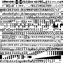
The card has two ROMs. One appears to be used for address decoding; the other is a 27C64 EPROM containing the font.
Memory Map
According to the review, there are three modes in which the card can be used:
- In native text mode, the card produces an 80×66 screen. This would match the brochure, which gives the character cell size as 15 pixels high and 9 wide, for a 720×990 pixel resolution. The framebuffer for this is at 0B0000h, as on a real MDA, but would have to be at least 2940h bytes long (the brochure says 16k).
- There is a dual-head mode, in which the top half of the screen shows a 25-line MDA display, and the bottom half the contents of the CGA framebuffer (graphical modes only?)
- Finally, there is the native graphics mode, 728×1008 pixels. Here, the framebuffer is divided into two segments. The first 512 lines live between 0A0000h and 0AFFFFh, the second 496 between 0B8000h and 0C7FFFh. Each line is 128 bytes long, though only the first 91 bytes are displayed. The reason for this slightly idiosyncratic split in the memory mapping is that the text in the MDA framebuffer (at 0B0000h) can optionally be superimposed on the graphic display.
Register I/O
Registers appear to be based on the standard MDA / CGA register set, with the following differences:
03B0h: CRT Control Register 2
The GEM and Windows drivers write 01h to this port to select the native graphics mode, 00h to return to text mode. They don't appear to do any sort of CRTC programming, which makes me think that perhaps this card doesn't have a reprogrammable CRTC — just a fixed set of timings.
The bits are defined in the manual as follows:
Bit 0: Set for MDS modes (66 lines text / 728×1008 graphics).
       Clear for IBM-compatible modes (25 lines text / 640×200 graphics).
Bit 1: If set, 'blink' attribute selects the second half of the character set
       (characters 256-511 as seen in the ROM dump)
Bit 2: Set for MDS enhanced character attributes, cleared for IBM-compatible
       character attributes. Set with GMC /M; cleared by mode set or GMC /I.
Bit 3: Set for 8×15 character cell. Clear for 9×15 character cell.
Bit 4: Set for reverse video graphics. Clear for normal video graphics.
Bit 5: Set for reverse video text. Clear for normal.
        GMC.COM (below) sets bits 4 and 5 to:
        00: Normal video
        01: 640x200 CGA-compatible graphics
        10: Reverse video
        11: 80x25 MDA-compatible text
Bit 6: Interrupt (IRQ2) at start of vertical retrace
Bit 7: Interrupt (IRQ2) at end of each line
If character attributes are IBM-compatible, the attribute byte is interpreted in a similar way to MDA:
Bit    7: Blink
Bits 6-4: Background (7 for reverse video, 0 for normal)
Bit    3: Bold
Bits 0-2: Foreground / underline (1 for underline, 0 for black, 7 for white)
With MDS enhanced attributes it is treated as:
Bit    7: Blink / extended character set
Bit    6: Alternate character set
Bits 5-4: Background colour (0=black 1=normal 2=dim 3=bold)
Bits 3-2: Foreground colour (0=black 1=normal 2=dim 3=bold)
Bits 0-1: Font effect (0=subscript 1=underline 2=superscript 3=normal)
03B1h: CRT Control Register 3
Bits 0-1: Character cell height
          00: 15 pixels
          01: 14 pixels
          02: 13 pixels
          03: 12 pixels
Bits 2-3: Always 0
Bit    4: Double height
Bit    5: Double width
Bit    6: Always 0
Bit    7: No reset of scroll register.
GMC.COM writes the following values to this port when selecting video mode:
00h: 66 lines text,  or GMC /H
81h: 70 lines text
83h: 82 lines text
90h: MDA-compatible, or GMC /S
93h: 41 lines text
03B4h-03B5h / 03D4h-03D5h: Emulated CRTC
GMC.COM and GMC_ANSI.SYS write to these CRTC registers:
0Ah: Cursor shape and blink rate (as on a real 6845):
	Bits 4-0: Top scanline
	Bits 6-5: Blink rate
03B8h: CRT Control Port 1 / MDA Mode Control Register
Only two bits of this register are used: Bit 3 (enable video) and bit 5 (enable blink). Bit 3 is set to 'enable' for text modes, 'disable' for graphics modes.
03D8h: Graphics Control Register / CGA Mode Control Register
Only bit 3 (Enable video) is used. Bit 3 is set to 'enable' for graphics modes, 'disable' for text modes.
The GEM and Windows video drivers access the mode control registers when switching in and out of the native graphics mode:
	mov	dx, 3D8h	;Graphics Control Register / CGA Mode Control
	mov	al, 8		;Enable display
	out	dx, al
	mov	dx, 3B8h	;CRT Control Port 1 / MDA Mode Control
	mov	al, 0		;Disable display
	out	dx, al
	mov	dx, 3B0h
	mov	al, 1		;Switch to graphics mode
	out	dx, al
and when switching back to text mode:
	mov	dx, 3D8h	;Graphics Control Register / CGA Mode Control
	mov	al, 0		;Disable display
	out	dx, al
	mov	dx, 3B8h	;CRT Control Port 1 / MDA Mode Control
	mov	al, 8		;Enable display
	out	dx, al
	mov	dx, 3B0h
	mov	al, 0		;Switch to text mode
	out	dx, al
In other words, to select graphics mode, disable the MDA display, enable the CGA display, and write 1 to 3B0h. To change back, disable the CGA, enable the MDA and write 0 to 3B0h. Windows skips enabling the MDA, and instead relies on a full mode set (INT 10h / AH=0) to re-enable it.
My guess is that enabling the MDA display shows the text framebuffer at B0000h, and enabling the CGA display shows the graphics framebuffer (either in native mode, or in CGA mode). The dual-head mode would then be achieved by enabling both displays simultaneously.
Driver
The Interrupt List documents a number of interrupts provide by VHRBIOS.SYS, a loadable driver which appears to serve as the card's BIOS ROM. It describes the driver as providing functions on INT 10h, including:
- AH=0F0h
- Installation check. Call with BX=0; returns BX=4F4Bh ('OK') if VHRBIOS.SYS is loaded. The Windows 1.04 driver checks that this call works before attempting to set the video mode. It does not appear to make any other calls to VHRBIOS.
- AH=0F1h
- Set reverse video. Call with AL=new video state; bit 5 set for black on white, clear for white on black.
- AH=0F4h
- Get driver version. Returns AX=driver version; AH=major, AL=minor.
- AH=0F5h
- Get vendor ID. Returns AX=4D44h ('MD'), BX=5349h ('SI').
This copyright registration also refers to a VHR_ANSI.ASM, the source code for a driver which (presumably) provides ANSI terminal emulation.
GMC_ANSI.SYS / INS_ANSI.SYS
What appear to be drivers for an MCA version of the card can be found at mpoli.fi. Two drivers are included which appear to be the equivalent of VHRBIOS.SYS: GMC_ANSI.SYS and INS_ANSI.SYS. The difference between them is that GMC_ANSI includes the full functionality of ANSI.SYS, while INS_ANSI (contrary to its name) is a minimal video BIOS with no support for ANSI escape codes.
Of the above calls, both drivers implement only AH=0F0h, but in different ways:
- AH=0F0h (GMC_ANSI)
- Installation check / disable mode changes. Call with BX=0, AL = 0 (enable mode changes) or AL nonzero (disable mode changes). Returns BX=4F4Bh ('OK') if GMC_ANSI.SYS is loaded.
- AH=0F0h (INS_ANSI)
- Installation check. Call with BX=0; returns BX=4F4Bh ('OK').
GMC.COM
GMC.COM is used to select the video mode. Its help screen does not list the full syntax, which is:
   GMC {mode{*}}{/options}

mode is one of:
OFF:  Disable Genius card, enable motherboard VGA
ON:   Enable Genius card, disable motherboard VGA
IBM:  Select MDA-compatible text mode, 80 x 25 text
CGA:  Select CGA-compatible graphics mode, 640 x 200 graphics
DUAL: Select both of the above modes, displayed one above the other
MDS:  Select native mode, 66 text lines
M41:  Select native mode, 41 text lines
M70:  Select native mode, 70 text lines
M82:  Select native mode, 82 text lines
If mode is followed by a *, attempts to change the video mode with INT 10h / AH=00h will be ignored until the next time GMC is used.
options are:
0-6: Set cursor blink rate
D:   Disable CGA-style graphics (implied by selecting MDA or native mode)
G:   Enable CGA-style graphics  (implied by selecting CGA or DUAL mode)
H:   Write 00h to port 03B1h    (single-height text; implied by selecting CGA, DUAL or MDS mode)
I:   IBM-compatible text attributes  (implied by selecting any mode)
M:   MDS extended text attributes
N:   Select black on white video
R:   Select white on black video (implied by selecting DUAL or native mode)
S:   Write 90h to port 03B1h     (double-height text; implied by selecting MDA mode)
John Elliott 27 November 2022