The Toshiba T3100e
The T3100e is a computer partway between the original luggable computers and a full laptop. It has a laptop form factor, but no batteries; it functions only when plugged into the mains.
The T3100 (no 'e') has a similar specification, but parts are not interchangeable — it isn't possible to put a T3100e motherboard in a T3100 case, or vice versa.
Hardware
The T3100e has the following features:
- 640×400 plasma display screen (amber on black).
- 3.5" floppy drive.
- 20Mb or 40Mb ATA hard drive.
- 1Mb - 5Mb onboard RAM.
- 82-key keyboard.
- Connectors for: external CGA monitor, parallel port or external floppy drive, two 9-pin serial ports, numeric keypad.
- An expansion bay allowing an 8-bit ISA card or proprietary Toshiba card to be fitted.
Floppy drive(s)
The internal floppy drive has a single 26-way connector carrying power and data. There are various discussions (1), (2), (3) of how to convert a standard 34-pin drive to use such a cable.
The third discussion above also gives the pinout for connecting an external drive to the parallel port, which I shall take the liberty of reproducing here:
                            CABLE PIN OUT


Toshiba  EXT FDD        SIGNAL NAME          Floppy Drive 34 Pin
  CONNECTOR                                  IDC CONNECTOR
    PIN                                           PIN

    01                  Ready                      34
    02                  Index                      08
    03                  Track 0                    26
    04                  Write Protect              28
    05                  Read Data                  30
    10                  Motor Enable A             10
    11                  Motor Enable B             16
    12                  Write Data                 22
    13                  Write Enable               24
    15                  Select Head 1              32
    16                  Direction                  18
    17                  Step Pulse                 20
    23                  Ground (must be connected) 23
    25                  Ground (must be connected) 25
BIOS battery
The BIOS battery is a 3.6v AA lithium battery, type ER14505. Replacement is not straightforward; it's soldered in series with a diode, and both are then plugged into the motherboard. Replacing it therefore requires the battery to be unsoldered — if you do this, take proper care not to let it overheat.
If you are replacing the battery, I recommend that rather than doing a straight 1:1 swap, you disconnect the leads from the old battery and attach them to a single AA holder. Then you can fit a conventionally-shaped AA battery (that doesn't use solder tags) so that future replacements don't need the soldering iron.
Jumpers
There are three jumpers on the motherboard, next to the socket for the external keypad. Normally they are all left open. From left to right, looking from the front of the case, they are:
- FD2
- If jumpered, two internal floppy drives fitted (both must be the same type). When the machines were designed, a twin-floppy system would have had no hard drive, but today it might be possible to replace the hard drive with a CompactFlash card and fit a second floppy in the hard drive bay. The motherboard doesn't have a second floppy socket, but there is a set of solder pads at position PJ9 where one would have to be fitted.
- FD2MB
- If jumpered, internal drive is ?tri-mode.
- F2HD
- If jumpered, internal floppy drive is 720k, not 1.4M.
A/B/PRT switch
There is a switch on the side of the computer, with three settings:
- A
- Drive A: is an external drive attached to the parallel port, and the internal drive is B:.
- B
- Drive B: is an external drive attached to the parallel port, and the internal drive is A:.
- PRT
- A printer is attached to the parallel port, and the internal drive is A:.
Memory
A T3100e has 1 megabyte of RAM on the motherboard, and four sockets for 30-pin SIMMs, allowing memory up to 5Mb. The SIMM sockets have a proprietary pinout, as described at the Vintage Computer Forum.
Additional memory (either EMS or XMS) can be provided by expansion cards.
This memory can be considered in three groups:
- Conventional memory: 512k or 640k
- Upper memory: 512k or 384k, depending how conventional memory is allocated. This can be used either as EMS or additional high memory.
- High memory: Everything past 1 megabyte.
To configure how memory is mapped, write a byte to I/O port 0x8084:
Bit 7: Always 0
Bit 6: Always 1
Bit 5: Always 0
Bit 4: Set if upper RAM is to be added to high memory, clear if it is to
       be treated as EMS.
Bit 3: Possibly used to enable add-on memory boards beyond 5Mb?
Bit 2: Set if conventional memory is 640k, clear for 512k.
Bit 1: Set to enable high memory.
Bit 0: Set to enable EMS memory.
The BIOS stores this memory configuration byte at 0040:0093h, and in CMOS memory at offset 0x37. If the top bit of the byte in CMOS is set, then high memory is being provided by an add-on card rather than the mainboard, and so the BIOS will not allow high memory to be used as EMS.
The bottom two bits of this byte are also stored in the top 2 bits of CMOS offset 0x3D.
EMS memory is controlled by 16 page registers:
| Page mapped at | 0xD0000 | 0xD4000 | 0xD8000 | 0xDC000 |
|---|---|---|---|---|
| Pages 0x00-0x7F | 0x208 | 0x4208 | 0x8208 | 0xc208 |
| Pages 0x80-0xFF | 0x218 | 0x4218 | 0x8218 | 0xc218 |
| Pages 0x100-0x17F | 0x258 | 0x4258 | 0x8258 | 0xc258 |
| Pages 0x180-0x1FF | 0x268 | 0x4268 | 0x8268 | 0xc268 |
So: OUT 0x208, 0x80 will page in the first 16k page at 0xD0000.
OUT 0x208, 0x00 will page out EMS, leaving nothing at 0xD0000
OUT 0x4208, 0x80 will page in the first 16k page at 0xD4000.
OUT 0x218, 0x80 will page in the 129th 16k page at 0xD0000.
etc.
The first 24 or 32 pages correspond to upper memory. Further pages are high memory, mapped from the end down. So on a 2Mb system with 384k upper memory, pages 0x00-0x17 would be upper memory, then page 0x18 would correspond to the last 16k of high memory, page 0x19 to the 16k below that, and so on.
To use EMS from DOS, you will need the Toshiba EMS driver (TOSHEMM.ZIP). This supports the above system, plus add-on EMS cards which appear to occupy similar ranges of ports at 0x_2A8, 0x_2B8 and 0x_2C8.
System configuration
The built-in video card and parallel port are controlled by writing to port 0x8084:
Bit 7: Always 1
Bit 6: Always 0
Bit 5: Always 0
Bit 4: Enable bidirectional parallel port
Bit 3: Disable internal CGA
Bit 2: Single-pixel font
Bit 1: }
Bit 0: } Display language
The bottom 5 bits match the bottom 5 bits of the configuration byte stored in CMOS at offset 0x3D. The last value written is saved at 0040:0015h.
Serial port configuration
The serial ports are also configured by writes to port 0x8084:
Bit 7: Always 0
Bit 6: Always 0
Bit 5: Always 0
Bit 4: Base address for whichever serial port ends up with IRQ5: 1 => 0x338, 0 => 0x3E8
Bits 3,2,0: Serial port IRQs for COM1, COM2 and COM3:
               00 0 => 4, 3, 5
               00 1 => 4, 5, 3
               01 0 => 3, 4, 5
               01 1 => 3, 5, 4
               10 0 => 4, -, 3
               10 1 => 3, -, 4
Keyboard
The built-in keyboard is an 82-key keyboard, using Alps mechanical keyswitches. Each key has a blocking diode in series with it, so that there isn't any crosstalk from holding down multiple keys. Should a key stop responding, the most likely cause is a failed blocking diode, which will have to be desoldered and replaced. A suitable replacement is the 1N914.
Of the 82 keys, 81 generate scancodes in the normal way. The exception is the 'Fn' key, which modifies the behaviour of other keys (converting letters into a substitute numeric keypad, for example).
There is an 8-pin mini-DIN socket on the left of the machine, which allows an external numeric keypad to be connected.
As well as accessing the BIOS, the [Fn] key also accesses a number of laptop-specific functions:
- Fn + PgUp
- Turbo on (power LED green)
- Fn + PgDn
- Turbo off (power LED red)
- Fn + Home
- Switch to internal display
- Fn + End
- Switch to external display
- Fn + RightArrow
- Toggle thick/thin font
- Fn + NumLock
- Toggle keypad overlay (keys 789 / UIOP / JKL; / M. act as a numeric keypad)
- Fn + F1
- F11
- Fn + F2
- F12
- Fn + Ctrl
- Right Ctrl
- Fn + Alt
- Right Alt
- Fn + Return
- Keypad Enter
Rather than generating scancodes, these keypresses are detected by the keyboard controller, which then notifies the BIOS by putting a nonzero value in the high nibble of the byte read from port 0x8084:
0	Normal, nothing to do
1	Fn + End         (Switch to external display)
2	Fn + down arrow  (no apparent effect)
3	Fn + PgDn        (turbo off)
4	Fn + Ins         (no effect)
5	Fn + Del         (no effect)
6	Fn + SysRQ       (no effect)
7	Fn + NumLock     (toggle keypad overlay)
8	Fn + ScrollLock  (no effect)
9	Fn + Home        (switch to internal display)
A	Fn + up arrow    (no effect)
B	Fn + PgUp        (turbo on)
D	Fn + left arrow  (no effect)
F 	Fn + right arrow (toggle thick/thin font)
Codes C and E are not returned, since no scancode is mapped to them in the keyboard controller firmware. Given the order of the other keys, C ought to be Fn + the extended equivalent of "Keypad +", and E should be Fn + the extended equivalent of "Keypad 5". Neither of these keys exists on a normal keyboard or the T3100e 82-key keyboard.
Code 2 appears to be for other hardware than the T3100e; its handler is part of a group of four functions that check for the signature "AGS" at C000:000A. The other three functions are the non-T3100e versions of 'Switch to internal display', 'Switch to external display' and 'toggle thick/thin font'. On the similar T3200, Fn + Down arrow changes the plasma screen between 350 and 400 lines, so that may be what this is attempting.
Having processed the notification, the BIOS sends command 0xBC to the keyboard controller to acknowledge it.
Keyboard Controller
The 8042 keyboard controller firmware was written by Award Software, and behaves very differently from the equivalent firmware on a genuine IBM PC. The following commands can be sent to port 64h; the ones marked * differ in their behaviour:
0x00-0x1F: * Ignored. On a real IBM this would read controller RAM.
0x20:        Read command register.
0x21-0x3F: * Ignored. On a real IBM this would read controller RAM.
0x40:        Write command register.
0x41-0x5F: * Ignored. On a real IBM this would write to controller RAM.
0x60:      * Ignored. On a real IBM this would write to the command register.
0x61-0x7F: * Ignored. On a real IBM this would write to controller RAM.
0x80-0xA9:   Ignored.
0xAA:	     Self test.
0xAB:	   * Interface test (always returns 0).
0xAC:      * Diagnostic dump. The first 4 bytes have fixed values, 'V230'
0xAD:        Disable keyboard.
0xAE:        Enable keyboard.
0xAF:        Ignored.
0xB0:      * Turbo on
0xB1:      * Turbo off
0xB2:      * Select external display
0xB3:      * Select internal display
0xB4:      * Return a byte giving turbo and display state, and floppy
             configuration.
		Bit 7: Active display (1 for plasma, 0 for external)
		Bit 6: Turbo mode (1 for 6MHz, 0 for full speed)
		Bit 5: Unknown (1 on my system)
		Bit 4: Set if the FD2MB jumper is present (internal floppy
                       drive is ?tri-mode)
		Bit 3: Zero if the FD2 jumper is present (two internal floppy
                       drives fitted)
		Bit 2: Set if the A/B/PRT switch is on B or PRT, clear if A
		Bit 1: Set if the A/B/PRT switch is on A or B, clear if PRT
		Bit 0: Set if the F2HD jumper is present (internal floppy
                       drive is 720k)
0xB5:      * Return a byte. The bottom bit of this is used to simulate the
             AT's colour / mono DIP switch (0 for colour, 1 for mono). The
	     other bits have no meaning to the keyboard controller and may be
             used by the BIOS for whatever it wants.
0xB6:	   * Set the byte to be returned by 0xB5.
0xB7:      * Reset the bottom bit of byte #21 (emulate PS/2 keyboard)
0xB8:      * Set the bottom bit of byte #21   (emulate AT keyboard)
0xB9-0xBA:   Ignored.
0xBB:	   * Returns a single byte.
	        Bit 1 is set if the keypad overlay is active.
		Bit 2 is the status of the [Fn] key (1 if key pressed).
                Other bits all zero.
0xBC:	   * Reset notification on port 0x8084.
0xBD-0xBF:   Ignored.
0xC0:      * Read input port. Returns all bits set except bit 6, which was
             set by the bottom bit of command 0xB5.
0xC1-0xC2: * Ignored (IBM uses for continuous input port poll)
0xC3-0xCF:   Ignored.
0xD0:        Read output port.
0xD1:        Write output port (bit 1 controls the A20 gate)
0xD2-0xDF:   Ignored.
0xE0:        Read test inputs.
0xE1-0xEF:   Ignored.
0xF0-0xFF:   Pulse output bits.
CMOS settings
The following CMOS locations have meanings not specified in the Interrupt List:
0x34  Byte  Checksum
0x35  Word  Size of conventional memory in kilobytes
0x37  Byte  Last memory configuration written to port 0x8084

0x3C  Byte  Expansion slot type and serial port settings
              Bits 6,7:   Expansion slot type
                          00 = none
                          01 = modem
                          10 = expansion chassis
                          11 = other
              Bit 4:      IRQ5 serial port base: 1 => 0x338, 0 => 0x3E8
	      Bits 3,2,0: Serial port IRQs for COM1, COM2 and COM3:
                          00 0 => 4, 3, 5
                          00 1 => 4, 5, 3
                          01 0 => 3, 4, 5
                          01 1 => 3, 5, 4
                          10 0 => 4, -, 3
                          10 1 => 3, -, 4
0x3D  Byte  T3100e settings
	      Bit 7: Enable high memory.
              Bit 6: Enable EMS memory.
	      Bit 5: Extended keyboard.
              Bit 4: Enable bidirectional parallel port.
              Bit 3: Disable internal CGA
              Bit 2: Single-pixel font
	      Bits 0,1: Display language
                          00 => Standard
                          01 => Northern European
                          10 => Canadian French
                          11 => Reserved
0x3F  Byte  Display attribute mapping (see INT 10h / AH = 70h)
Hard drive
The BIOS only supports two hard drive geometries:
- Type 11
- 20Mb: 615 cylinders, 4 heads, 17 sectors
- Type 12
- 40Mb: 980 cylinders, 5 heads, 17 sectors
Any other drive geometry would require the use of a dynamic drive overlay.
Expansion bay
The expansion bay on the underside of the laptop allows an expansion card to be fitted, either using a Toshiba proprietary connector, or what looks like a standard 8-bit ISA connector.
One of the expansion options is a full-on expansion chassis. This allows other video cards to be connected; if a card (such as CGA or VGA) is fitted that conflicts with the built-in display, the built-in display will be deactivated.
BIOS
The BIOS is written by Award Software. It appears to support at least four types of computer, selected by a model number at F000:FFFA. The T3100e is model 44, but there are frequent checks for models 45 and 47. Bit 3 of all these numbers is 1; if it were to be zero, the BIOS would run code for a 386 rather than a 286.
Other Toshiba laptops seem to use the same model numbering system. I'm aware of the following model numbers:
T1600:  43
T1000:  44  (machine type at F000:FFFE is 0FEh [XT] rather than 0FCh [AT])
T1200:  45
T1100+: 46
T5200C: 47
To enter the BIOS setup screen hold down the 'Fn' key during boot. Version 1.70 of the BIOS can also be invoked from DOS: launch DEBUG and type G=F000:4000
The following INT 10h functions are provided; these seem to be common to several Toshiba laptops:
INT 10h / AH = 70h: Return display type and attribute mapping. Returns:
			AH = attribute mapping, 0-15
				Bits 0,1 for characters 001h-006h,008h-00Eh (colour on black)
				Bits 2,3 for characters 011h-017h,019h-01Fh
							021h-027h,029h-02Fh
							...
							0F1h-0F7h,0F9h-0FFh (colour on colour)
				Mapping values are: 0 for normal
				                    1 for inverse video
				                    2 for bold
				                    3 for bold and inverse
			AL = display type (0 => plasma, 1 => CRT, 2 => LCD)

INT 10h / AH = 71h: Set display attribute mapping. Enter with
			AL = attribute mapping (bits 0-3)
			Bit 7 of AL set to persist setting to CMOS.
The default attribute mapping as set up by the BIOS is 4: Characters 00xh are shown as normal, characters 01xh, 02xh are shown in reverse video.
The Toshiba utility CHAD can be used to change these mappings from the command line. It takes two parameters from 1 to 4; the first controls the 011h-0FFh range, and the second controls the 001h-00Eh range.
Video Hardware
The screen is a 640×400 plasma display.
There are multiple different mappings for the text attributes, controlled by the low 4 bits of CRTC register 12h. These contain the attribute mapping as described above under INT 10h / AH = 70h.
The following mapping is the default, as set up by the BIOS. For attributes 80h and above, the mapping depends whether blinking is enabled or not. With blinking disabled, the attributes are:
| 00 | 01 | 02 | 03 | 04 | 05 | 06 | 07 | 08 | 09 | 0A | 0B | 0C | 0D | 0E | 0F |
| 10 | 11 | 12 | 13 | 14 | 15 | 16 | 17 | 18 | 19 | 1A | 1B | 1C | 1D | 1E | 1F |
| 20 | 21 | 22 | 23 | 24 | 25 | 26 | 27 | 28 | 29 | 2A | 2B | 2C | 2D | 2E | 2F |
| 30 | 31 | 32 | 33 | 34 | 35 | 36 | 37 | 38 | 39 | 3A | 3B | 3C | 3D | 3E | 3F |
| 40 | 41 | 42 | 43 | 44 | 45 | 46 | 47 | 48 | 49 | 4A | 4B | 4C | 4D | 4E | 4F |
| 50 | 51 | 52 | 53 | 54 | 55 | 56 | 57 | 58 | 59 | 5A | 5B | 5C | 5D | 5E | 5F |
| 60 | 61 | 62 | 63 | 64 | 65 | 66 | 67 | 68 | 69 | 6A | 6B | 6C | 6D | 6E | 6F |
| 70 | 71 | 72 | 73 | 74 | 75 | 76 | 77 | 78 | 79 | 7A | 7B | 7C | 7D | 7E | 7F |
| 80 | 81 | 82 | 83 | 84 | 85 | 86 | 87 | 88 | 89 | 8A | 8B | 8C | 8D | 8E | 8F |
| 90 | 91 | 92 | 93 | 94 | 95 | 96 | 97 | 98 | 99 | 9A | 9B | 9C | 9D | 9E | 9F |
| A0 | A1 | A2 | A3 | A4 | A5 | A6 | A7 | A8 | A9 | AA | AB | AC | AD | AE | AF |
| B0 | B1 | B2 | B3 | B4 | B5 | B6 | B7 | B8 | B9 | BA | BB | BC | BD | BE | BF |
| C0 | C1 | C2 | C3 | C4 | C5 | C6 | C7 | C8 | C9 | CA | CB | CC | CD | CE | CF |
| D0 | D1 | D2 | D3 | D4 | D5 | D6 | D7 | D8 | D9 | DA | DB | DC | DD | DE | DF |
| E0 | E1 | E2 | E3 | E4 | E5 | E6 | E7 | E8 | E9 | EA | EB | EC | ED | EE | EF |
| F0 | F1 | F2 | F3 | F4 | F5 | F6 | F7 | F8 | F9 | FA | FB | FC | FD | FE | FF |
When blinking is enabled, the mapping is slightly different:
| 00 | 01 | 02 | 03 | 04 | 05 | 06 | 07 | 08 | 09 | 0A | 0B | 0C | 0D | 0E | 0F |
| 10 | 11 | 12 | 13 | 14 | 15 | 16 | 17 | 18 | 19 | 1A | 1B | 1C | 1D | 1E | 1F |
| 20 | 21 | 22 | 23 | 24 | 25 | 26 | 27 | 28 | 29 | 2A | 2B | 2C | 2D | 2E | 2F |
| 30 | 31 | 32 | 33 | 34 | 35 | 36 | 37 | 38 | 39 | 3A | 3B | 3C | 3D | 3E | 3F |
| 40 | 41 | 42 | 43 | 44 | 45 | 46 | 47 | 48 | 49 | 4A | 4B | 4C | 4D | 4E | 4F |
| 50 | 51 | 52 | 53 | 54 | 55 | 56 | 57 | 58 | 59 | 5A | 5B | 5C | 5D | 5E | 5F |
| 60 | 61 | 62 | 63 | 64 | 65 | 66 | 67 | 68 | 69 | 6A | 6B | 6C | 6D | 6E | 6F |
| 70 | 71 | 72 | 73 | 74 | 75 | 76 | 77 | 78 | 79 | 7A | 7B | 7C | 7D | 7E | 7F |
| 80 | 81 | 82 | 83 | 84 | 85 | 86 | 87 | 88 | 89 | 8A | 8B | 8C | 8D | 8E | 8F |
| 90 | 91 | 92 | 93 | 94 | 95 | 96 | 97 | 98 | 99 | 9A | 9B | 9C | 9D | 9E | 9F |
| A0 | A1 | A2 | A3 | A4 | A5 | A6 | A7 | A8 | A9 | AA | AB | AC | AD | AE | AF |
| B0 | B1 | B2 | B3 | B4 | B5 | B6 | B7 | B8 | B9 | BA | BB | BC | BD | BE | BF |
| C0 | C1 | C2 | C3 | C4 | C5 | C6 | C7 | C8 | C9 | CA | CB | CC | CD | CE | CF |
| D0 | D1 | D2 | D3 | D4 | D5 | D6 | D7 | D8 | D9 | DA | DB | DC | DD | DE | DF |
| E0 | E1 | E2 | E3 | E4 | E5 | E6 | E7 | E8 | E9 | EA | EB | EC | ED | EE | EF |
| F0 | F1 | F2 | F3 | F4 | F5 | F6 | F7 | F8 | F9 | FA | FB | FC | FD | FE | FF |
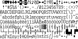
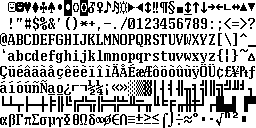
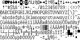
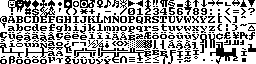
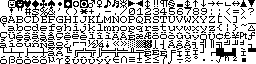
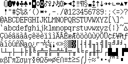
There are four hardware fonts, each with 'normal' and 'bold' variants:
| Codepage 437 | |
|---|---|
 |
 |
| North European | |
 |
 |
| French Canadian | |
 |
 |
| Reserved | |
 |
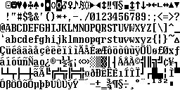 |
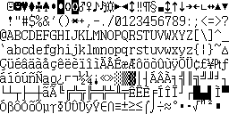
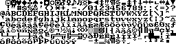
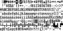
When the display is set to an external monitor, an alternate set of 8×8 fonts is used. Again, the fonts come in bold and non-bold variants. For doubtless good reasons, the font selection mechanism works in reverse: When the internal display is set to use the thin font, the external display uses the bold font, and vice versa.
| Codepage 437 | |
|---|---|
 |
 |
| North European | |
 |
 |
| French Canadian | |
 |
 |
| Reserved | |
 |
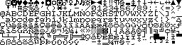 |
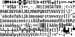
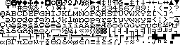
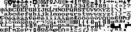
For graphics modes, the BIOS ROM contains the following fonts. Note the difference in the 'smiling face' characters 1 and 2, compared to the font ROM:
| 8×16 thin | 8×16 thick |
|---|---|
 |
 |
| 8×8 thick | 8×8 thin (partial) |
 |
The thin 8×8 font does not appear to be used; graphics modes always draw in the thick font.
As mentioned above, the low 4 bits of CRTC register 12h give the attribute mapping. Bits 4 and 5 are used by INT 10 / AH = 70h to determine the display type:
Bit 5 is zero => CRT    (type 1)
Bit 4 is zero => LCD    (type 2)
Both are 1    => Plasma (type 0)
Video modes
The display supports the standard CGA modes 0-6. Modes 4 and 5 display the colours as dither patterns, with each CGA pixel occupying four plasma pixels. Colours are:
0       1       2       3
B B     A B     A B     A A
B B     B B     B A     A A

(A=> Amber, B=> Black)
In all modes bar mode 6, the CGA colour control register is ignored completely. In mode 6, setting the low 4 bits of the colour control register to 0 blanks the display.
The BIOS also supports a 640×400 video mode, which is invoked by requesting modes 40h or 74h. Behind the scenes, this mode is activated by programming the CGA for 640×200, and then setting the 6845 character height register to 3 rather than 1.
In this mode, as with a Hercules card, the display lines are divided into four groups, at offsets 0000h, 2000h, 4000h and 6000h in video RAM. So lines 0,4,8,12... are in the block at 0000h, lines 1,5,9,13... are in the block at 2000h and so on.
It is also possible to set up an undocumented 320×400 video mode by selecting mode 40h and then turning off high resolution in the CGA control register.
Attempting to use the 640×400 mode with an external CGA monitor will result in a signal that the monitor cannot display.
John Elliott 28 October 2017