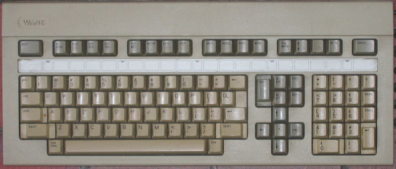
Wang PC Keyboard
Note: You need a browser capable of displaying SVG images to see the keyboard layouts.
The Wang PC was a non-IBM compatible MSDOS PC (my specimen dates from 1985 or so). Its incompatibility extends to the keyboard, which differs in layout, pinout and communication protocol.
Here is the pinout of the keyboard socket (viewed from outside the case):
Note that unlike the IBM PC keyboard, which has a bidirectional data line and a separate clock line, this keyboard has two unidirectional data lines. The one I have designated 'Receive' (coloured yellow) is for transmission from the keyboard to the host PC; the 'Send' line (coloured white) is for transmission from the host to the keyboard.
Hardware
The keyboard circuit board is branded 'Keytronic'.
The microcontroller used is an 8051.
The keyswitches are foam-and-foil switches. Considering how old these keyboards are by now, it's quite likely that the foam has disintegrated, meaning that the keys no longer register. If so, it can be replaced with double-sided sticky pads.
Wire Protocol
The transmission protocol used is (as far as I can see) something like RS-232 (but using TTL voltages, which I think makes it RS423). At the keyboard end, communication is handled by the 8051's built-in UART.
A bit is roughly 16μs long. The 8051 is placed in 9-bit mode, with the ninth bit always 1 on both transmit and receive.
If a key is not configured to send key-up scancodes, then after it is pressed the transmit line will be held low (as shown) until it is released. If it is configured to send key-up codes, the transmit line is left high after the stop bits are sent.
Scancodes
The keyboard returns the following scancodes:
When the keyboard powers-up, only the two Shift keys (shaded grey) send key-up scancodes (as on an XT, this is indicated by having bit 7 set). All the others send key-down scancodes and then pull the 'Receive' wire low until the key is released.
The four pads shown with dotted outlines do not have keys above them, but return scancodes if pressed on the circuit board. One of them (shaded orange) transmits the same scancode as the right-hand Shift.
The scancodes shown in blue belong to unused pads under double-sized keys.
The technical reference manual also describes a variant with five extra keys:
- 1D
- Between left Shift and Z
- 20
- Where 1F is on the standard keyboard; 1F moves to between = and Backspace.
- 21
- Between [ ] and GL
- 22
- Between ' " and Return
- 23
- Between . > and / ?
Keyboard Commands
Bytes can be transmitted to the keyboard using the same protocol and timings, but on the 'Send' wire rather than the 'Receive'. Commands are:
| 00 | No-op. |
| 01 nn | These commands set a list of keys that return key-up scancodes, replacing any previous such list. The two Shift keys need not be included in the list as they will always return key-up scancodes. |
| 02 nn nn | |
| 03 nn nn nn | |
| 04 nn nn nn nn | |
| 05 nn nn nn nn nn | |
| 06 | Set all keys to return key-up scancodes. |
| 07 | Set only the two Shift keys to return key-up scancodes (as at power-on). |
| 08 | Reset the keyboard. |
| 09 | Keyboard ID. Two scancodes will be sent to the host: 01h (Acknowledge) followed by 34h (identity). |
| 0A | Key click. |
| 0B | Beep. |
| 0C | Repeat last scancode sent. |
| 0D | No-op. |
| 0E | Return status of DIP switches. Three scancodes will be sent to the host: 01h (Acknowledge), then the state of the left-hand switch bank, then the state of the right-hand bank. Bit 7 in a byte corresponds to the left-hand switch. |
| 0F | Return beeper / keyclick volume as set by command 20h. Two scancodes will be sent to the host: 01h (Acknowledge), followed by the volume. |
| 10 | Turn on LED 1 (Lock key) |
| 11 | Turn off LED 1 |
| 12 | Turn on LED 2 |
| 13 | Turn off LED 2 |
| 14 | Turn on LED 3 |
| 15 | Turn off LED 3 |
| 16 | Turn on LED 4 |
| 17 | Turn off LED 4 |
| 18 | Turn on LED 5 |
| 19 | Turn off LED 5 |
| 1A | Turn on LED 6 |
| 1B | Turn off LED 6 |
| 1C | Turn on all LEDs |
| 1D | Turn off all LEDs |
| 1E | Get LED status. Two scancodes will be sent to the host: 01h (Acknowledge), followed by a byte giving the state of the LEDs. Bit 0 = LED 1, Bit 1 = LED 2 and so on. |
| 20 xx | Set beeper / keyclick volume. Bits 0-2 give beeper volume, 0=mute Bits 3-5 give keyclick volume, 0=mute |
| 31 xx | Program the keyboard's SN76489AN sound generator. These are used in the self-test to make the keyboard speaker emit different tones. The parameters control the pitch. |
| 32 xx xx |
John Elliott 27 June 2011.