Hercules Graphics Card Plus: Notes
The Hercules Graphics Card Plus is an extension to the original Hercules Graphics Card, allowing redefinable fonts in text mode.
- Hardware requirements
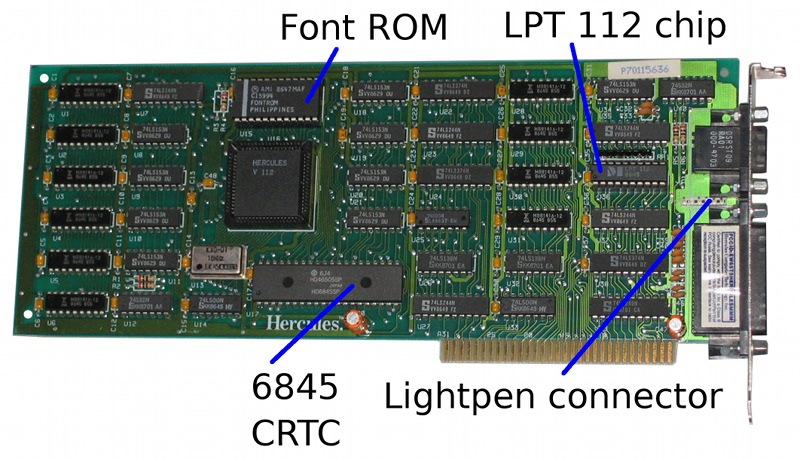
- The hardware
- Memory Map
- Register I/O
- Memory Access
- Character attributes
- Recommended CRTC values
- The printer port
Hardware requirements
The card is an 8-bit ISA card containing the display controller and a printer port. When present in a computer, it requires the following system resources:
- 4k-64k of RAM at address 0B0000h.
- I/O addresses 03B0h-03BFh.
- The printer port uses IRQ7.
The hardware
Output is from a DE9 socket. The pinout of this socket is:
- Ground
- Ground
- Not used
- Not used
- Not used
- Intensity
- Video
- Horizontal sync
- -Vertical sync
The font rom is marked AMI C15994 FONTROM (the same ROM is used on the Hercules InColor card). As on the original IBM MDA, this is a 9264 rather than a 2764, so it can't be read in a standard EPROM programmer. The memory layout isn't the same as on the MDA, so you can't swap the chip with one from an MDA and expect it to make sense. Both ROMs are divided into four 2k blocks; on the MDA, the font is in blocks 0 and 1, but here it is in blocks 1 and 3.
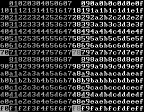
The card uses the 14-pixel font in the ROM:
![[14-pixel Hercules Plus font]](Images/hercplus.png)
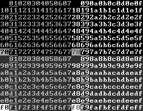
The ROM also contains two 8-pixel fonts (in blocks 0 and 2) which do not appear to be used.
![[8-pixel Hercules Plus fonts]](Images/hercplus8.png)
Memory Map
On power-up, the HGC+ behaves like an MDA, producing an 80×25 text screen in white on black. Each character is 9 pixels wide and 14 high, giving a 720×350 pixel resolution. Although the characters are 9 pixels wide, the bitmaps in the ROM (or the RAM) only cover the first 8. For characters 0C0h-0DFh, the ninth pixel column is a duplicate of the eighth; for others, it's blank.
In text mode, the usual MDA-esque scheme is used, with two bytes of RAM for each character. The first byte is the character code, and the second gives the attribute.
The HGC+ outputs four possible combinations of video signal:
| Video | Intensity | Resulting 'colour' |
|---|---|---|
| 0 | 0 | Black |
| 0 | 1 | Dim |
| 1 | 0 | Normal |
| 1 | 1 | Bright |
(Depending on the monitor, dim may display the same as black. On the monitor I used for testing, a dim background looked the same as black, but normal characters on it appeared slightly brighter. I've tried to replicate that on the illustrations below).
On startup, the character attribute scheme behaves like an MDA:
- Bits 2-0: 1 for underline.
- Bit 3: Foreground colour is bright.
- Bit 7: If blinking is enabled: Blink. Else: Background colour is dim.
with eight exceptions:
- Attributes 00h and 08h display as black space.
- Attributes 80h and 88h display as dim space.
- Attribute 70h displays as black on normal.
- Attribute 78h displays as dim on normal.
- Attribute F0h displays as a blinking version of 70h (if blinking is enabled); as black on bright otherwise.
- Attribute F8h displays as a blinking version of 78h (if blinking is enabled); as dim on bright otherwise.
| Blink enabled | Blink disabled |
|---|---|
 |
 |
Register I/O
03B4h: CRTC address register.
Write a CRTC register number (0 to 1Ch) to this port to select the CRTC register that will appear at port 03B5h. Registers 0-11h are standard 6845 registers and are described on the 6845 datasheet.
Registers 14h-16h are used to control the HGC+'s additional features, and are described below.On the MDA, the CRTC address and data register are partially decoded, so that any even-numbered address between 03B0h and 03B7h will get you the CRTC address register, and any odd-numbered address gets you the data register. I don't know whether this holds for the HGC+.
This is a write-only register.
03B5h: CRTC register read/write.
This gives access to the selected CRTC data register. Most CRTC registers are write only; some are read/write or read-only.
03B8h: Mode Control Register
This is a write-only register. The following bits are used:
Bit 7: Graphics page to display
If bit 7 is 1, the graphics page at 0B8000h is displayed. Otherwise, the page at 0B0000h is displayed.
Bit 5: 1 to enable blinking, 0 to disable it.
If bit 5 is 1, characters with attribute bit 7 set will blink. If not, they will have high intensity background.
Bit 3: 1 to enable video output, 0 to disable it.
If bit 3 is 0, screen output will not be shown. The usual use of this is if you're reprogramming the CRTC registers; disable video output beforehand and re-enable it after.
Bit 1: 1 for graphics mode, 0 for text.
When the card is switched between text and graphics modes, the 6845 must be reprogrammed with suitable parameters for the new mode.
03B9h: Set light pen flip-flop
Any write to this port sets the flip-flop.
03BAh: Status Register
This is a read-only register.
- Bit 7: 0 if vertical sync active, 1 if inactive.
- Bits 6-4: Card ID (001b = 1 for HGC+). The manual advises programs checking for HGC+ features to test only the bottom 2 bits; that way, they'll also work on an InColor card (ID 101b = 5).
- Bit 3: Video. This is 1 if a pixel is being drawn on the screen at this moment.
- Bit 1: Light pen flip-flop.
- Bit 0: Retrace. This is 1 if the horizontal retrace is active.
03BBh: Reset light pen flip-flop
Any write to this port resets the flip-flop.
03BFh: Graphics mode enable
This is a write-only register.
- Bit 1: Set to page in the upper 32k of memory at 0B8000h, clear to page it out.
- Bit 0: Set to allow graphics mode, clear to disallow it. Also enables access to memory from B1000h to B7FFFh.
Additional CRTC registers
The additional CRTC registers are:
Register 14h: xMode
This is a write-only register, initialised to 0 on reset. The following bits are used:
Bit 0: 0 to use ROM font, 1 to use RAM font.
If the RAM font is selected, character bitmaps are read from 0B4000h. Each bitmap holds 16 bytes per character; the top 14 (normally) are drawn.
Bit 1: 0 for 80-column mode, 1 for 90-column mode.
If this bit is changed, the first four CRTC registers need to be reprogrammed. For 80-column mode, they should be set to 61 50 52 0F, and for 90-column mode they should be set to 6D 5A 5C 0F.
In 90-column mode characters are 8 bits wide, and so there is no special treatment of characters 0C0h-0DFh.
Bit 2: 0 for 4k RAMfont, 1 for 48k RAMfont
In 48k RAMfont mode, the low 4 bits of the attribute byte become a font selector, 0-11 (Values 12-15 render as vertical stripes). This selects the font used for drawing: font 0 is at B4000h, font 1 is at B5000h and so on.
Register 15h: Underline
This is a write-only register, initialised to 0Dh on reset. It only applies in 48k RAMfont mode; it sets the position of the underline for underlined characters. Bits 3-0 give the row (0-15).
Register 16h: Strikethrough
This is a write-only register, initialised to 0Dh on reset. It behaves as underline, for characters with the 'strikethrough' attribute.
Character Attributes
There are two ways the card can interpret character attributes. In normal text mode or in the 4k RAMfont mode, they behave like an MDA (as described above). In the 48k RAMfont mode, the semantics are different. The low 4 bits become a font number, 0-11 (with 12-15 giving characters composed of random vertical stripes) and the high 4 bits give the attribute:
| Blink on | Bit 7=High intensity Bit 6=Blink Bit 5=Strikethrough Bit 4=Underline |
|---|---|
| Blink off | Bit 7=Boldface Bit 6=Reverse video Bit 5=Strikethrough Bit 4=Underline |
Recommended CRTC values
Hercules graphics cards do not include any form of BIOS extension, and the standard IBM BIOS treats them as an MDA. Consequently, to switch between text and graphics modes (or 80- and 90- column modes), the CRT controller has to be reprogrammed manually. These values should be set at the same time as the text/graphics bit in the Mode Control register, or the 80/90 column bit in the xMode register.
In the tables below, all values are in hexadecimal.
| Register | 80-column text | 90-column text | Graphics |
|---|---|---|---|
| 00 Horizontal total | 61 | 6D | 35 |
| 01 Horizontal displayed | 50 | 5A | 2D |
| 02 Horizontal blanking | 52 | 5C | 2E |
| 03 Sync width | 0F | 0F | 07 |
| 04 Vertical total | 19 | 19 | 5B |
| 05 Vertical adjust | 06 | 06 | 02 |
| 06 Vertical displayed | 19 | 19 | 57 |
| 07 Vertical sync position | 19 | 19 | 57 |
| 08 Interlace and skew | 02 | 02 | 02 |
| 09 Max raster | 0D | 0D | 03 |
| 0A Cursor start | 0B | 0B | 00 |
| 0B Cursor end | 0C | 0C | 00 |
The manual also provides timing values for different character heights, allowing (for example) a 43-line display with 8-pixel characters. In this situation, a suitable font of the correct height should be loaded into RAM.
| Register | Character height | ||||||||||||
|---|---|---|---|---|---|---|---|---|---|---|---|---|---|
| 4 | 5 | 6 | 7 | 8 | 9 | 10 | 11 | 12 | 13 | 14 | 15 | 16 | |
| 04 Vertical total | 5C | 4A | 3D | 34 | 2D | 28 | 24 | 20 | 1D | 1B | 19 | 17 | 16 |
| 05 Vertical adjust | 02 | 00 | 04 | 06 | 02 | 01 | 00 | 07 | 0A | 06 | 06 | 0A | 02 |
| 06 Vertical displayed | 58 | 46 | 3A | 32 | 2B | 26 | 23 | 1F | 1D | 1A | 19 | 17 | 15 |
| 07 Vertical sync position | 59 | 46 | 3B | 33 | 2C | 27 | 23 | 20 | 1D | 1B | 19 | 17 | 16 |
The printer port
According to the manual, the printer port can be disabled (if it conflicts with another piece of hardware) by removing the chip marked HCT LP112 adjacent to the port.
The printer port behaves like the one on an MDA:
- Write to port 03BCh: Set data lines.
- Read from port 03BCh: Reads last value sent to printer.
- Read from port 03BDh: Get printer status.
- Bit 3: ~Error
- Bit 4: Select
- Bit 5: Paper out
- Bit 6: ~Acknowledge
- Bit 7: Busy
Bits 2 and 0 always appear to be 1. Bit 1 varies between 0 and 1.
- Write to port 03BEh: Set control lines.
- Bit 0: ~Strobe
- Bit 1: ~Auto Feed
- Bit 2: Initialize printer
- Bit 3: ~Select input
- Bit 4: Enable interrupt when the printer sets ~Acknowledge to 0.
- Read from port 03BEh: Reads bits 4-0 of last value written. The top 3 bits always appear to be 1,1,1.
John Elliott 9 August 2012