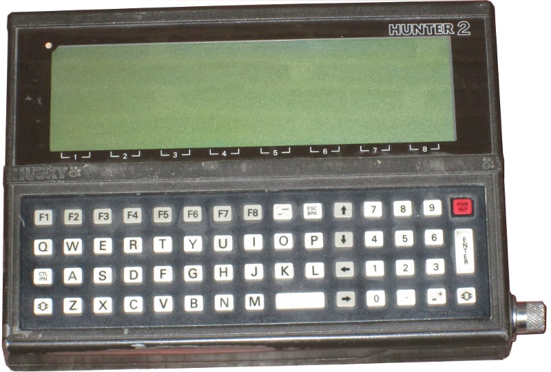
The Husky Hunter 2
Note: This page is mainly based on dumping the ROMs of a Hunter 2 that no longer boots; so there's a fair bit of guesswork that I haven't been able to test on a working computer.
Hardware
The Husky Hunter 2 is a small portable computer, designed to be rugged and reasonably waterproof. The case is sealed with a rubber gasket, and the interior contains a packet of silica gel to keep it dry.
Power is provided by four AA batteries, or an external power supply. An internal rechargeable battery maintains the memory while the main batteries are being changed; if that runs down, the computer won't boot. Letting it recharge from the main batteries overnight may help to bring the computer back to life.
The hardware includes:
- CPU: NSC800N (a clone of the Z80 with extra features).
- 240×64 pixel liquid crystal display.
- Sockets for up to 6 ROM chips. My example has two 32k ROMs, 64k in total, suggesting a maximum of 192k ROM.
- 128k-736k RAM.
- 25-pin serial port. There is no UART; the port is driven by direct bit-banging from the processor.
- Real Time Clock.
Memory Map
The Z80's 64k of address space is divided into three windows:
| C000 | Common RAM memory |
|---|---|
| 8000 | Banked ROM or RAM |
| 4000 | ROM 0 or RAM |
| 0000 |
Memory paging is accomplished by writing to port 0E0h.
Values written are:
| Value | At 0000 | At 4000 | At 8000 | At C000 |
|---|---|---|---|---|
| 00-09 | ROM 0 | Banked ROM. Low 4 bits of value give bank: 0 => ROM 1, first 16k 1 => ROM 1, second 16k 2 => ROM 2, first 16k 3 => ROM 2, second 16k etc. | Common RAM | |
| 80-8F | Banked RAM. Low 4 bits of value give the bank to use. | |||
Keyboard
The keycaps on my Hunter don't really seem to match the ASCII that the system ROM generates. The Hunter pictured here seems a much closer match for the codes I'm getting.
The keyboard matrix is a 7×8 grid, laid out like this:
| Column | 0 | 1 | 2 | 3 | 4 | 5 | 6 | 7 |
|---|---|---|---|---|---|---|---|---|
| Row | ||||||||
| 0 | 6 | 5 | Y | T | G | F | B | V |
| 1 | 8 | 7 | I | U | J | H | M | N |
| 2 | 0 | 9 | P | O | L | K | Comma | Space |
| 3 | Esc/Brk | Up | Right | Lbl/Ins | Enter | Down | Backspace | Tab |
| 4 | = | - | Left | [ | ' | ; | / | . |
| 5 | 2 | 1 | W | Q | A | Ctrl | Z | Shift |
| 6 | 4 | 3 | R | E | D | S | C | X |
The ROM also contains a second, smaller, key table, for the SP and M-208. This has one fewer row and omits the cursor and symbol keys, and lower-case letters. Unshifted letter keys generate capital letters, and shift+letter generates a symbol. The matrix for this keyboard is:
| Column | 0 | 1 | 2 | 3 | 4 | 5 | 6 | 7 |
|---|---|---|---|---|---|---|---|---|
| Row | ||||||||
| 0 | 6 | 5 | Y | T | G | F | B | V |
| 1 | 8 | 7 | I | U | J | H | M | N |
| 2 | 0 | 9 | P | O | L | K | Space | |
| 3 | Enter | |||||||
| 4 | 4 | 3 | R | E | D | S | C | X |
| 5 | 2 | 1 | W | Q | A | Ctrl | Z | Shift |
I/O Ports
The following I/O port ranges are used:
00-1F: NSC810 I/O and Timer
The NSC810 provides timing for the serial port, and access to the keyboard.
| Address | Meaning | Notes |
|---|---|---|
| 00 | Port A Data | On input: Reads the current keyboard matrix row(s) as selected by writing to port B, (see below). Results are active low, 0 if key pressed. |
| 01 | Port B Data | On input: Bit 7 gives state of RS232
DSR line. On output: Used to select keyboard matrix row. To read a single row, enable output on only one bit, and write 0 to that bit. For example, write 02h to port 5, then ~(02h) = 0FEh to port 1. At end of keyboard read, write 7Fh to port 5 and 80h to port 1; reads from port 0 then check all rows. |
| 02 | Port C Data | On input:
Bit 0 gives state of RS232 data received line? Bit 1 gives state of RS232 DCD line. Bit 2 set if battery low? Bit 3: ? Bit 5: Power button pressed? |
| 04 | Data Direction Register A | Initialised to 0 (all lines input) |
| 05 | Data Direction Register B | Initialised to 7Fh (bit 7 input, others output) |
| 06 | Data Direction Register C | Initialised to 20h (bit 5 output, others input) |
| 07 | Mode Definition Register | Initialised to 0 (normal mode) |
| 08 | Port A: Clear bit(s) | Write the mask of bits to clear |
| 09 | Port B: Clear bit(s) | Write the mask of bits to clear |
| 0A | Port C: Clear bit(s) | Write the mask of bits to clear |
| 0C | Port A: Set bit(s) | Write the mask of bits to set |
| 0D | Port B: Set bit(s) | Write the mask of bits to set |
| 0E | Port C: Set bit(s) | Write the mask of bits to set |
| 10 | Timer 0 low | |
| 11 | Timer 0 high | |
| 12 | Timer 1 low | |
| 13 | Timer 1 high | |
| 14 | Stop timer 0 | |
| 15 | Start timer 0 | |
| 16 | Stop timer 1 | |
| 17 | Start timer 1 | |
| 18 | Timer 0 mode | |
| 19 | Timer 1 mode |
The timer runs at the same speed as the CPU, 4MHz.
If the serial port is set to use IBM 2780 protocol, then timer 0 is used in one-shot mode with prescale = 2. Otherwise it's used in 'event counter' mode to provide the transmit baud timings.
Timer 1 provides the receive baud timings.
20-3F: HD61830 LCD Controller
The Hunter uses an HD61830 to drive its LCD screen. The processor can only update the screen by sending commands to the HD61830 through its I/O ports; the HD61830's video RAM is internal to it and does not appear in the Z80's memory space.
| Address | Meaning |
|---|---|
| 20 | On read: Busy if bit 0 is set. Before accessing any other port
check that bit 0 of this register is 0. On write: Parameter for current command. |
| 21 | On write: Command. All commands bar 0Dh are followed by a write to port 20h with the parameter for the command. |
| 3E | Byte read from screen by command 0Dh. The HD61830 datasheet cautions that a correct value is only returned on the second read. |
Commands are:
| Command | Notes |
|---|---|
| 00 | Mode control. Bits in value include:
Bit 1: Graphics mode Bit 5: Display enabled |
| 01 | Set character dimensions. Bits in value are:
Bits 2-0: Character width - 1 Bits 7-4: Character height - 1 |
| 02 | Set width of screen in characters. value is width - 2. |
| 03 | Set time divisions. |
| 04 | Set cursor row. value is position of cursor in character cell. |
| 08 | Set address of screen start in framebuffer (low byte). |
| 09 | Set address of screen start in framebuffer (high byte). |
| 0A | Set address of cursor in framebuffer (low byte). |
| 0B | Set address of cursor in framebuffer (high byte). |
| 0C | Write value to video RAM at the cursor location, and increment the cursor location by 1. |
| 0D | Read video RAM at the cursor location. Value will be returned through port 3Eh. |
| 0E | Clear a bit in video RAM at the cursor location, and increment the cursor location by 1. value gives the number of the bit. |
| 0F | Set a bit in video RAM at the cursor location, and increment the cursor location by 1. value gives the number of the bit. |
40-4F: MM58174A Real-Time Clock
The clock's 15 4-bit registers are visible to the Z80 as:
40: Test register
41: Tenths of a second
42: Seconds low  (BCD digit)
43: Seconds high (BCD digit)
44: Minutes low  (BCD digit)
45: Minutes high (BCD digit)
46: Hours low    (BCD digit)
47: Hours high   (BCD digit)
48: Days low     (BCD digit)
49: Days high    (BCD digit)
4A: Day of week  (BCD digit)
4B: Months low   (BCD digit)
4C: Months high  (BCD digit)
4D: Leap year shift register
4E: Start/stop
4F: Interrupt
60: LCD backlight and contrast
I'm more or less guessing from the code, but it looks as if the bit mapping is:
Bit 2: Backlight toggle
Bits 1,0,7,6: Contrast level.
80-86: Serial port and system control
80: Written by NMI handler — presumably a handshake line of some kind.
81: Bit 0 = transmit data line
82: Bit 0 = CTS?
83: First action of the boot ROM is to write 55h to this port. Later on
    in the boot process, 1 is written.
    Write 0 to power off.
84: Bit 0 = RTS
86: Bit 0 controls the beeper.
BB: NSC800 interrupt control register
Bit 0 = Enable normal interrupts
Bit 1 = Enable RSTC interrupts
Bit 2 = Enable RSTB interrupts
Bit 3 = Enable RSTA interrupts
The INT interrupt is used only in IBM 2780 communications.
As far as I can see, the RSTC interrupt is used when the serial port is using CTS handshaking. It fires when the CTS signal is received, and signals the NMI handler to start transmitting a character (if there is one).
The RSTB interrupt appears to fire when activity is detected on the serial port's receive line. The interrupt handler sets up the correct baud rate on timer channel 1; the RSTA handler then deals with decoding the bits as they come in.
The RSTA interrupt is connected to timer channel 1, and fires when the timer reaches 0. When receiving a byte from the serial port, it is used to generate bit timings. Otherwise it is runs at its minimum speed, approximately 61Hz.
The NMI is connected to timer channel 0, and fires when the timer reaches 0. This is used in serial output; the NMI timing matches the rate at which bits should be transmitted.
DEMOS
The operating system is DEMOS (in my case, DEMOS 2.21 build 9G08h V4), which uses an API moderately compatible with CP/M 2.2. Extra BDOS functions are used to access Hunter-specific facilities.
DEMOS supports CP/M BDOS calls, but there is no BIOS jumpblock or separate CCP.
For a program running under DEMOS, the memory map is as follows:
| E000 | DEMOS resident portion (corresponding to CP/M BDOS) |
|---|---|
| DF80 | Operating system variables |
| D800 | 80×24 character buffer — the LCD is used to display a 6×40 window into this area. |
| D700 | DEMOS jumpblock. First jump is to BDOS entry point. |
| 0100 | Program |
| 0000 | Zero page |
DEMOS Filesystem
Memory banks 1+ are used for the RAMdisc. Each memory bank is laid out as:
| 0800 | Data blocks |
|---|---|
| 0100 | Directory |
| 0040 | [in bank 1 only] Used space bitmap, 1 bit / block |
| 0000 | Interrupt vectors |
Unlike in a real CP/M filesystem, the directory is spread across however many RAM banks there are, with 56 entries in each bank.
The filesystem uses 2k blocks; block nn is at address ((nn * 0x800) & 0xFFFF) in RAM bank (nn / 0x20). This means block numbers are not contiguous across the filesystem; blocks 0x00-0x1F correspond to the TPA, 0x20 / 0x40 / 0x60 etc to the directory zones, 0x38-0x3F / 0x58-0x5F / 0x78-0x7F etc to common memory. In the used space bitmap, these blocks will be marked as used.
A DEMOS directory entry is formed:
UU F1 F2 F3 F4 F5 F6 F7 F8 T1 T2 T3 EX S1 S2 RC   .FILENAMETYP....
AL AL AL AL AL AL AL AL AL AL AL AL AL AL AL AL   ................

UU is 0 for a valid file, 0E5h for a deleted file. DEMOS does not support
CP/M user numbers.
Fn - filename
Tn - filetype. File attributes as for CP/M 2.2.
EX - Extent counter, for files more than 16k in size.
S1 } Extent checksum on last read.
S2 } Extent checksum on last write.
AL - Eight 16-bit words giving the numbers of 2k blocks containing the file
    data.
The checksum is an 8-bit sum, calculated on the first 2047 bytes of each block covered by this extent. A file may only be 128 bytes long, but the checksum covers the entire 2k block containing it (omitting the last byte).
When an extent is opened its S1 checksum is calculated. If this does not match the S2 checksum recorded by the last save, the attempt to open the file will fail.
DEMOS jumpblock
The jumpblock at D700h is an approximation to the CP/M BIOS jumpblock:
	jp	0E000h	;DEMOS entry point
	jp	bdos0	;Wrapper for BDOS function 0
	jp	wboot	;Launch command processor
	jp	const	;Get console status
	jp	conin	;Read character with no echo
	jp	conout	;Console output, C = character.
	jp	list	;Output to serial port, C = character.
	jp	punch	;Output to serial port, C = character.
	jp	reader	;Input from serial port
	jp	home	;Returns A=0
	jp	seldsk	;Returns A=0
	jp	settrk	;Returns A=0
	jp	setsec	;Returns A=0
	jp	setdma	;Sets DMA address in BC
	jp	read	;Wrapper for BDOS function 14h, and not in any way
			;the low-level sector read that the CP/M BIOS provides.
	jp	write	;Wrapper for BDOS function 15h, and not in any way
			;the low-level sector write that the CP/M BIOS provides.
Z80 restarts and other addresses in low memory
- RST 0
- Cold boot. This code occupies 5 bytes, so there is no I/O byte or current CCP drive. Since there is no jump at 0000h, programs which expect to find the address of the BIOS at 0001h will not work correctly.
- CALL 5
- BDOS entry
- RST 8
- RST 38h followed by a jump to the BDOS entry point.
- RST 10h
- Does not exist; falls through to RST 18h
- RST 18h
- Page in the ROM and call it. Inline word parameter is address to call.
- RST 20h
- Page in the disk BDOS and call it. Inline word parameter is address to call.
- 0027h
- Computer model. 0xFF => Hunter 2, 0x7F => SP, others => M-208
- RST 28h
- JP (HL)
- 002Ch
- RSTC interrupt: Serial port transmit character.
- RST 30h
- Debug break -- enter builtin monitor.
- 0034h
- RSTB interrupt: Serial port commence receive.
- RST 38h
- Used only by IBM 2780 communucations.
- 003Ch
- RSTA interrupt: Timer 1 handler.
Notes on BDOS calls
NB: The BDOS function number is not range-checked. Passing an out-of-range function number in C will result in a crash.
- 04h
- Output a byte to the serial port. If the system is configured to echo serial output to the screen, the byte will be echoed.
- 07h
- Get IOBYTE. Only two bits in the IOBYTE have effect: bit 7 is set if console input is coming from the serial port, bit 6 set if console output is going to the serial port.
- 0Eh
- Ignored. DEMOS only supports one drive.
- 20h
- Ignored. DEMOS only supports user 0.
- 26h
- Clear input buffers.
- 27h
- Built-in time set routine. Prompts for date and time, sets the clock.
- 29h
- Built-in serial port setup routine. Prompts for transmission speed and protocols.
- 2Ah
- Poll the serial port for input. If input is waiting returns A=0FFh, Zero not set. If not, A=0, Zero set.
- 2Bh
- Load a file through the serial link.
- 2Ch
- Modified version of line input (function 0Ah).
- 2Dh
- Transmit an area of memory down the RS232 link in Intel .HEX format. IX = address, DE = length.
- 2Eh
- Read an Intel .HEX file from the RS232 link into memory.
- 2Fh
- Read a character from the keyboard without echoing it to the screen.
- 30h
- Read the real-time clock (if it has been set).
- 31h
- Load BDOS and run overlay. DE points to the overlay FCB; the first byte is the overlay number. Overlays are 1536 bytes long and load at E72Bh; the first byte of the overlay is also its number.
- 32h
- Used in IBM-2780, Systime and ACK/NACK serial configurations.
- 33h
- Append the character in E to the serial port output queue, and start the timer for transmission.
- 34h
- Call the vector at FABCh.
- 35h
- Read a line from the serial port into buffer at F403h. Ends at 96 bytes, or when a CR is received, whichever is first.
- 36h
- Get serial transmit buffer status. If buffer is full, returns A=0, Zero set; otherwise A=0FFh, Zero reset.
- 37h
- Display serial communications error.
John Elliott 16 February 2014