The Toshiba T1000
The T1000 is an XT-class laptop from 1987. Its specification and form factor are similar to the IBM Convertible. What makes the T1000 unusual is that it includes a copy of MS-DOS 2.11 in ROM.
There are at least two versions of the BIOS: 026C (BIOS v1.10, 29 June 1987) and 026F (BIOS v4.10, 2 May 1988). I have worked from the later BIOS when writing this page.
Detecting a T1000
The supplied programs use various techniques, but the best seems to be to check the BIOS ROM. The byte at F000:FFFE should be 0FEh (machine class is XT) and the byte at F000:FFFA should be 2Ch.
The byte at F000:FFFA is also 2Ch in other Toshiba laptops, such as the T3100e, but in the case of the T3100e the machine class is 0FCh (machine class is AT).
Other Toshiba laptops seem to use the same model numbering system. I'm aware of the following model numbers:
T1600:  43
T1000:  44
T3100e: 44  (machine type at F000:FFFE is 0FCh [AT] rather than 0FEh [XT])
T1200:  45
T1100+: 46
T5200C: 47
Jumpers
The motherboard has five jumpers:
- PJ17
- ROM drive size. Pins 1-2 for a 512k ROM, 2-3 for 128k or 256k ROM.
- PJ18 / 19
- ROM chip type. Pins 1-2 if the ROM chip has address 16 on pin 2 and enable on pin 24 (like the 27C040). Put the jumper on pins 2-3 if the ROM chip has these two pins reversed (like the Toshiba TC571001 / Hitachi 27C301).
- PJ20 / PJ21
- Font select. If both are closed, display font is codepage 437. If PJ21 is open, display font is Danish. Some motherboards (including mine) don't have PJ20, so I've no idea what might happen if it's opened.
The ROM drive
Physically, the ROM drive is a 256k or 512k chip sitting in the motherboard alongside the BIOS ROM. In my T1000 it was a TC534000P chip, which my EPROM programmer could read using 27C040 settings. Despite being labelled as a 512k chip, it could well have been a 256k chip since what came out of it was two copies of a 256k ROM image.
Access to the ROM drive is accomplished by output to port 0C8h. Bit 7 of the value written is 1 to page the ROM in at A0000h, 0 to page it out. The remaining bits select which 64k range of the ROM should appear at A000:0000. This mechanism would allow a ROM drive of up to 8Mb, but the hardware doesn't support more than 512k.
There are at least two versions of the ROM DOS: R2A20US and R2A22US. The ROM chips containing these are marked 9062 and B004 respectively. Differences include:
- EMM.SYS, the EMS driver
- CHAD.COM, controlling screen attribute contrast
- Dummy files (named DUMMY1 / DUMMY2 on the earlier ROM, DUM and KB1000\DUM on the later).
- Keyboard drivers (in the KB1000 subdirectory)
- SELECT.EXE (generate CONFIG.SYS) is version 2.20 in the earlier ROM, 3.20 in the later.
Contents
The contents of the ROM drive consist of a 1k header, followed by a FAT12 filesystem (unlike a hard drive, it is not partitioned). The BIOS parameter block is identical to that used for a standard DOS 713k floppy; since the ROM is actually smaller than 713k, a dummy file occupies all the clusters that are 'off the end' of the ROM. In theory other formats could be used, but they must have 9 sectors per track, because that figure is hardcoded in the BIOS.
The ROM header has the following format:
00-02	DB	0, 0, 4		;ROM size, bytes. Mine is 256k.
03-05	DB	1, 2, 3		;Head, Sector and Cylinder of CONFIG.SYS file.
				;The BIOS may, if configured appropriately,
				;replace the first 160 bytes of this sector
				;with data from non-volatile RAM.
06-08	DB	0, 5, 20	;Head, Sector and Cylinder of AUTOEXEC.BAT
				;file. The BIOS does not seem to have a
				;similar substitution mechanism for this
				;sector; possibly it was provided for future
				;expansion.
09-0A	DW	checksum	;16-bit checksum of the ROM image, excluding
				;the first 1024 bytes. Note that this checksum
				;is stored in big-endian order; so 45DCh would
				;be stored as 45h, DCh rather than the usual
				;Intel order of DCh, 45h.
0B-3FF	Does not appear to be used; can be filled with FFh bytes.
The ROM BIOS performs one other patch, at a different location depending on the size given in the ROM header. If the size is 256k, the patch applies when reading from offset 3A121h; if it's 128k, the offset is 19921h. Either way, the 5-byte sequence it inserts is:
B8 00 4C	MOV	AX, 4C00h
CD 21		INT	21h
This patch appears to fall in one of the keyboard drivers, and I'm not sure of its purpose.
Creating an alternative ROM drive
I have written two programs to convert from a normal disc image (or real floppy) to a ROM image, or vice versa.
![]() t1000rom.zip
contains a download for DOS, plus source for any platform with a functioning
LibDsk.
t1000rom.zip
contains a download for DOS, plus source for any platform with a functioning
LibDsk.
If you want to do it manually, this USENET article describes how to program a new ROM drive image. Some of the steps given can be simplified by (for example) using a dedicated disc imaging tool rather than DEBUG, or loopback-mounting a disc image under Linux.
CONFIG.SYS storage
As mentioned above, when asked to read CONFIG.SYS from the ROM drive, the BIOS can substitute a version from battery-backed RAM. This is handled by I/O ports 0C0h - 0C3h:
0C0h: When writing data: The first byte written is 0FFh, then the 160 bytes to
      store. When reading data 00h is written to this port and then the mode
      is changed from write to read.
0C2h: Input. Returns next byte.
0C3h: On output: Set mode.
		00h => idle.
		80h => write.
		40h => read.

      On input: status.
		Bit 0 = 1 when next byte ready to be read.
		Bit 1 = 1 when next byte ready to be written.
		Bit 4 (at least in idle mode) is floppy changeline
		Bits 6,7 = mode, as output.
      The test program TEST10 requires the status to be 06Fh when the next
      byte is ready to be read, 0AEh when the next byte is ready to be
      written. That implies bits 2,3,5 are always 1.
Procedure when reading is:
OUT 0C3h, 80h	;Set write mode
OUT 0C0h, 00h	;Possibly this resets the read/write address.
Wait for bit 1 of IN 0C3h to be 1.
OUT 0C3h, 40h	;Set read mode.
For 160 bytes: Wait for bit 0 of IN 0C3h to be 1, then read byte from IN 0C2h.
OUT 0C3h, 00h	;End reading.
Procedure when writing is:
OUT 0C3h, 80h	;Set write mode
OUT 0C0h, 0FFh;	;Begin writing
For 160 bytes: Wait for bit 1 of IN 0C3h to be 1, then OUT 0C0h, byte.
OUT 0C3h, 00h	;End writing
Keyboard
There are 82 keys, of which 81 generate normal scancodes. The remaining key is the 'Fn' key, which modifies the behaviour of the following keys.
Note that some of the keystrokes below have no meaning on the T1000, but are detected presumably because the T1000 shares components with the T1200.
- Fn + PgUp
- No effect ('Turbo on' on the T1200)
- Fn + PgDn
- No effect ('Turbo off' on the T1200)
- Fn + Home
- Switch to internal display
- Fn + End
- Switch to external display
- Fn + RightArrow
- Toggle LCD font
- Fn + NumLock
- Toggle keypad overlay
- Fn + F1
- F11
- Fn + F2
- F12
- Fn + Ctrl
- Right Ctrl
- Fn + Alt
- Right Alt
- Fn + Return
- Keypad Enter
- Fn + SysRQ
- No effect ('Toggle pop-up window' on the T1200)
Some of these keys set or clear bits in port 0E1h:
Bit 7: Set if 'turbo off', clear if 'turbo on'
Bit 6: Set if external display, clear if internal display
Bit 5: Set for thin LCD font, clear for thick LCD font
Bit 4: Set for keypad overlay on, clear for keypad overlay off
Bit 3: Set for 'pop-up window', clear if not
Bit 2: Pressed state of Fn key
Bit 1 }
Bit 0 } Unknown, always appear to be 0.
The BIOS copies bits 2 and 4-7 of the last value read from port 0E1h to port 0E2h; this seems to be so it can detect changes in the value read. I don't know the purpose of bits 0,1 and 3 of port 0E2h.
There is a socket for an external numeric keypad. This is a simple 2-pin serial connection, not the 8-pin connector used on the T3100e.
The LCD
There are two extra INT 10h functions to support the video hardware:
- AH=70h
- Returns the current display type and attributes:
- AH = attribute mapping. Bits 2-3 for colour on colour, bits 0-1 for colour on black.
- AL = display type: 0 for plasma, 1 for CRT, 2 for LCD.
- AH=71h
- Set contrast settings in AL. Bits 2-3 for colour on colour, bits 0-1 for colour on black. If bit 7 of AL is set, save these values to CMOS as defaults.
The four possible options for each contrast setting are 0 for normal, 1 for inverse, 2 for high-intensity normal, 3 for high-intensity inverse.
At a hardware level, CRTC register 12h contains these settings. The top four bits are read-only and give the display type (bit 5 reset for CRT, bit 4 reset for LCD, both set for plasma) while the bottom four hold the contrast settings and are read-write.
The system control ports 0E3h and 0E4h are used to switch between the internal display and an external CRT, and to choose the font used. Write 5Ah to port 0E3h, followed by a byte to 0E4h with:
Bit 4 set: Num Lock LED? (The T1000 does not have a Num Lock LED, but the
           T1200 does. The BIOS writes the value of the Num Lock flag at
           0040:0017 to this bit.)
Bit 5 set: Thin font.
Bit 6 set: External display.
Bit 7 set: 'Turbo' on.
Although the T1000 has no turbo mode, the BIOS still checks bit 7 of this port when accessing floppy discs; if the bit is set, then a timing loop is run twice as many times.
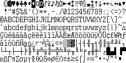
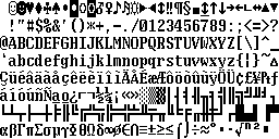
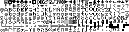
Font ROM
The font ROM is a surface-mounted TC53257 ROM. According to the hardware manual this is an 8k chip, but the TC53257 datasheet gives the correct size of 32k.
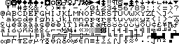
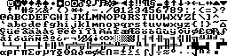
The chip contains two fonts, each in 'normal' and 'bold' variants, and 8×8 and 8×16 sizes. The 8×16 fonts are not used by the T1000.
| Codepage 437 | |
|---|---|
 |
 |
 |
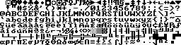 |
| Danish | |
 |
 |
 |
 |
The Real Time Clock / CMOS RAM
The RTC is a TC8521, which is a 4-bit chip. The chip is visible at I/O ports 2C0h - 2CFh.
For the full specification, see the datasheet at datasheetarchive.com. In the T1000, the data storage is used as follows:
- Page 0 (timer)
- Contains system date and time.
- Page 1 (alarm)
- Not used.
- Page 2 (RAM)
-
2C0: Set to 5 to indicate 'RAM contents valid'. 2C2: Bits 0, 1: Display type (1 for CGA40, 2 for CGA80, others default to CGA80) 2C3: Bit 2 = built-in RS232 port (1 for COM1, 0 for COM2) Bit 0 = printer port bidirectional 2C4: Bit 1 = keyboard emulation (0 for 101 keys, 1 for 84 keys). Bit 2 = 1 to use memory copy of CONFIG.SYS when booting from ROM drive. Bit 3 = 1 to extend conventional RAM to 640k (if an EMS board is present). 2C5: EMS hardware address: 0 for 208h, 1 for 218h, 2 for 258h, 3 for 268h, 4 for 2A8h, 5 for 2B8h, 6 for 2E8h, 7 or higher to disable EMS 2C6-7: The BIOS treats these two fields as a byte, but does not use the byte for anything. 2C8-9: Hard RAM size / 64k. 2CA: Display contrast settings (as returned in AH by INT 10h/AH=70h) 2CB-C: 8-bit checksum of values from 2C2h-2CAh. Stored big-endian, so 2CBh holds high nibble and 2CCh holds low nibble. - Page 3 (RAM)
- 2C4h holds boot device: 0 for RAMdrive, 1 for floppy, 2 for ROM.
Whenever the PAGE register at 2CDh is being written, bits 2 and 3 are always 0 and 1, respectively (enable clock, disable alarm).
Memory Expansion Board
The T1000 can be expanded with a battery-backed 768k memory board. The 768k RAM can be used for up to three purposes:
- 128k can be used to increase conventional memory to 640k.
- Some or all of can be used as a persistent RAM disk ('Hard RAM').
- The remainder, if any, can be used as EMS memory.
How the memory is divvied up is controlled by the I/O ports at 0EEh (register select) and 0EFh (data):
| Register | On read | On write |
|---|---|---|
| 50h | Low 4 bits: EMS I/O port. 0 => 0208h, 1 => 0218h
etc. If set to 7 or 0Fh this disables EMS and hard RAM. High 4 bits: Always 9 to indicate presence of the memory card. The test program TEST10 also checks for 8, which may indicate a memory card that isn't battery-backed. |
Low 4 bits: EMS I/O port. High 4 bits ignored, write 0. |
| 51h | Low 5 bits: Start address of EMS within the card RAM,
divided by 64k (00h-0Ch). Memory below this address is used
for conventional / hard RAM; memory above it, if any, is used
for EMS. High 3 bits: EMS page frame address: 0 => 0C400h, 1 => 0C800h, 2 => 0CC00h etc. |
Low 5 bits: Start address of EMS within the card RAM. High 3 bits ignored, write 0. |
| 52h | Bit 7: Set to use the first 128k of the
memory card as conventional memory. The programmer is
responsible for setting the EMS start address higher than
2 (ie, 640k) to avoid overlap. Other bits ignored. | |
| 00h | The BIOS and test program always select register 0 at the end of an operation involving the memory card, thus rendering the registers less liable to change at the hands of a random program. | |
The test program (but not the BIOS) also checks for the presence of a second memory card on the same ports, but using registers 60h - 61h.
Hard RAM
The hard RAM is presented as a second hard drive (D:). To access it, the BIOS moves the start of EMS memory to the start of the area designated as hard RAM, and uses standard EMS operations to read and write it.
Internally, the RAM is formatted as a standard FAT filesystem, 16k less than the memory allocated for the purpose. The last 16k contains checksums for each 512-byte 'sector'. The checksums are verified at boot; if they are incorrect, the user is warned that the hard RAM is unreadable and must be reformatted.
Although the hard RAM is presented as a hard drive, it doesn't have a partition table; it contains only a DOS partition. If you want to install a later version of DOS on it, you'll need to use that version's FDISK and FORMAT to set up a partition table.
Hardware Problems
There are a couple of common hardware problems that affect the T1000:
Battery Pack Replacement
The T1000 will not boot without its rechargeable battery pack present. This consists of four NiCad cells in series, size 'Cs'. RS Components part number 377-7927 is a suitable cell from which to make replacement battery packs.
The battery pack is connected to the mainboard by a four-way cable; the two red leads connect to the positive terminal of the first cell, the two black leads to the negative terminal of the last cell.
Motherboard capacitors
The usual symptom of capacitor failure is that when the laptop is turned on, the power LED illuminates red, then green for about a second, then goes out. In some cases it may remain lit, but the laptop does not power up. A 'fishy' smell is also a good indication that at least one capacitor has blown.
The problem is most likely in one of the large capacitors on the motherboard. If one of these shows obvious signs of bulging or leakage, that's most likely the culprit. If none of them do, you may have to replace all of them to find the guilty party.
C120: 25v / 220µF
C121: 10v / 470µF
C122: 35v / 150µF
C123: 25v / 220µF
C500: 25v / 100µF
Desoldering the original capacitors is a difficult job, because the mainboard is tightly packed and it's all too easy to damage adjacent components. It's certainly not a task for an amateur.