Wyse WY-700
The Wyse WY-700 is a CGA-compatible video adapter from the 1980s. Where the CGA's maximum pixel resolution is 640 × 200, the WY-700 can go up to 1280 × 800.
Rather than the CGA's 16 colours, the WY-700 displays four shades of grey.
The Hardware
Physically, the adapter is composed of two full-length ISA cards bolted together. The bottom card contains the MC6845 CRTC, and an MC68705P3 microcontroller. The top card has two jumpers marked 'COLOR' and 'MONO', and two EPROMs containing the font.
The 'COLOR' and 'MONO' jumpers are used to allow the card to be used alongside a CGA or MDA card (or a motherboard video chipset compatible with these). If the card is installed on its own, both jumpers should be turned on. To install alongside an MDA, switch off 'MONO', and to install alongside a CGA, switch off 'COLOR'.
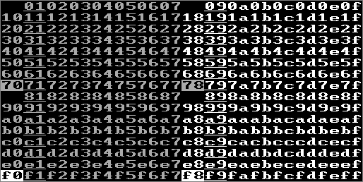
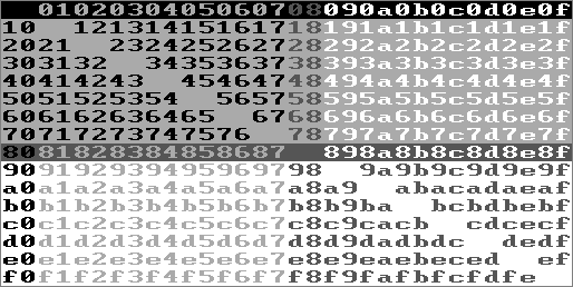
The card contains two 16×16 pixel fonts. The 'Left' character ROM contains the left-hand 8 pixels for all 512 characters, and the 'Right' character ROM contains their right-hand 8 pixels. The default fonts are:
![[WY-700 default fonts]](Images/wy700font.png)
Supported modes
According to its manual, the modes supported by the card are:
| Text/Graphics | Resolution | Mono/Greyscale | Character size (pixels) | Notes |
|---|---|---|---|---|
| Text | 80×25 | mono | 16×32 | Compatible with MDA mono (mode 7) |
| Text | 80×25 | 4 greys | 16×32 | Compatible with CGA greyscale (mode 2) |
| Text | 40×25 | 4 greys | 32×32 | Compatible with CGA greyscale (mode 0) |
| Text | 80×50 | 4 greys | 16×16 | |
| Text | 160×25 | mono | 8×32 | |
| Text | 160×50 | mono | 8×16 | |
| Graphics | 320×200 | 4 greys | Compatible with CGA greyscale (mode 5) | |
| Graphics | 640×200 | mono | Compatible with CGA mono (mode 6) | |
| Graphics | 320×400 | 4 greys | ||
| Graphics | 640×400 | 4 greys | ||
| Graphics | 1280×400 | mono | ||
| Graphics | 1280×800 | mono |
The high-resolution text modes (80×50, 160×25, 160×50) are not implemented in hardware, but are provided by the SCREEN.EXE utility. This selects the 1280×800 graphics mode, and then provides its own implementation of the BIOS INT 10h text output functions to draw characters.
Screen Attributes
If the 'character height' 6845 register is set to 1 or 14, screen attributes will emulate the MDA:
- Bit 1: Underline
- Bit 3: High intensity
- Bit 7: Blink (if bit 5 of port 03B8h is reset).
If blink is enabled, attributes 80-FF are the same as 00-7F, but blinking.
If the 'character height' register is set to any other value, screen attributes emulate the CGA:
Again, if blink is enabled, attributes 80-FF are the same as 00-7F, but blinking.
In the CGA-compatible 4-colour modes (modes 4 and 5), the colour mapping is straightforward: 00 => black, 01 => dark grey, 02 => light grey, and 03 => white. The 2-colour mode displays foreground as light grey, background as black; in both cases, the CGA colour register (0x3D9) has no effect.
Provided Utilities
The original manual describes four utilities as being supplied with the card:
- CLEAR.EXE
- Clear the screen in 160-column or 50-line text modes, replacing CLS.
- FONT.EXE
- Switch between the two fonts supported by the card.
- SAVER.EXE
- A TSR screensaver utility.
- SCREEN.EXE
- A TSR that implements the large-screen text modes, and also allows selection of standard text modes so it can replace MODE.
A fifth utility, PSCREEN, implements PrintScreen support for the high-resolution screen for Epson, HP LaserJet and HP ThinkJet printers.
Memory Map
The following memory ranges are used:
A0000 - AFFFF: High-resolution modes (only mapped in when a high-res mode is
               selected)
B0000 - B3FFF: MDA-compatible text mode
B8000 - BBFFF: CGA-compatible text and graphics modes
According to the programmer's manual, the same physical memory is used for all video modes, so you shouldn't access the CGA/MDA framebuffers while in high-resolution mode.
Register I/O
The registers are a superset of those used by the CGA and MDA. CGA and MDA registers (3B0h-3BFh and 3D0h-3DCh) are read/write, rather than write-only as on real IBM hardware. This is also the case for the CRTC registers (accessed through ports 3B4h-3B5h / 3D4h-3D5h).
The 'CRTC' presented to the PC is not the physical CRTC on the card. This cannot be accessed directly from the PC; the 68705 microcontroller programs it according to the currently-selected video mode.
In addition to the standard CGA/MDA registers, there are three write-only registers to control the extra features:
- 03DDh
- Address of top scanline (low byte)
- 03DEh
- Address of top scanline (high byte)
- 03DFh
- Control register (write only). The programmer's manual
only documents its behaviour in high-resolution graphics modes:
Bit    7: Always 1 in graphics mode.
Bits 6-4: Mode:
		0 => 640×400 mono
		1 => 320×400 greyscale
		2 => 1280×400 mono
		3 => 640×400 greyscale
		4 => 1280×800 mono
		5 => 640×800 greyscale
		6, 7 reserved.
Bit    3: In high-resolution mode, set to enable display, clear to disable it.
          In CGA- or MDA- compatible modes, set to 0.
Bit    2: Always 0 in graphics mode.
Bit    1: Memory bank to write in 800-line modes: 0 for even lines, 1 for odd lines
Bit    0: Memory bank to read  in 800-line modes: 0 for even lines, 1 for odd lines
When the hardware is in one of the high-resolution graphics modes, a write to the CGA/MDA control register or any access to the CRTC registers (for example, to set the cursor position) will switch back to the appropriate CGA-compatible or MDA-compatible mode.
This register also behaves as a command register when the values 01-07 are written to it:
01: Unblank screen, leave ?diagnostic mode, select default (thick) font
02: Select default (thick) font
03: Select alternative (thin) font
04: Appears to enter a diagnostic mode; the cursor no longer responds to
    commands to change its position, and its blink rate (and the blink rate
    of flashing text) increases. When I try this on my card, further writes
    to the command register have no effect (microcontroller crash, or
    self-test failed?).
05: Judging by the microcontroller ROM, should leave the ?diagnostic mode.
06: Blank the screen.
07: Unblank the screen.
In the 800-line modes, only half the framebuffer can be visible in the A0000-AFFFF range at one time, so the bottom two bits of this port select which half is mapped there. The 400-line modes have a straightforward linear framebuffer, rather than CGA-esque interleaving.
In the 640×400 mode and 320×400 modes, a screen occupies 32k, and so two video pages can be fitted in the framebuffer at A0000. To switch between them, the start address (ports 3DDh / 3DEh) can be set to 0000h for the first page, or 2000h for the second page.
The programmer's manual describes how to calculate the top scanline address. In 400-line modes, it's the offset of the scanline in video RAM, divided by 4. In 800-line modes, it's the offset divided by 4 and then multiplied by 40 — suggesting that the maximum offset supported is 6552.
Drivers
SCREEN.EXE, when resident, provides the following additional modes to INT 10h / AH = 0:
AL=0C0h: 80×25
AL=0C1h: 80×50
AL=0C2h: 160×25
AL=0C3h: 160×50
As mentioned above, these modes are actually implemented using the 1280×800 graphics mode.
Driver floppies also existed with drivers for GEM 1.2, GEM 2.1, GEM 2.2, Windows 1 and Windows 2.
WY-700 drivers were provided with GEM 3.0 and 3.1. An updated version of this driver, with codepage support, can be found in the FreeGEM driver packs.
A WY-700 driver existed for Windows 3.0 (wyse700.zip) and for WordPerfect 6 for DOS (wys700.exe -> wys700.vrs).
This list of 5.25" discs includes mentions of what may be WY-700 drivers for AutoCAD (DSWY700.DRV), Orcad II (WYSE700A.DRV / WYSE700B.DRV / WYSE700C.DRV), Windows/286 (WYSE700.DRV), Word 5 for DOS (WYSE700.CSD / WYSE700.GSD), and Bitstream fonts 2.05 (WYSE700.DDF).
Emulation
PCE has partial emulation of this card, enough to support the GEM and Windows drivers.
PCEM has a reasonably full emulation of the card.
John Elliott 10 June 2025