Sigma Designs Color 400
The Color 400 is a graphics card that was designed to compete with the EGA. It provides the features of a CGA card, with the addition of three new video modes: 80×30 text, 80×50 text and 640×400 graphics in 16 colours.
Table of contents
Hardware
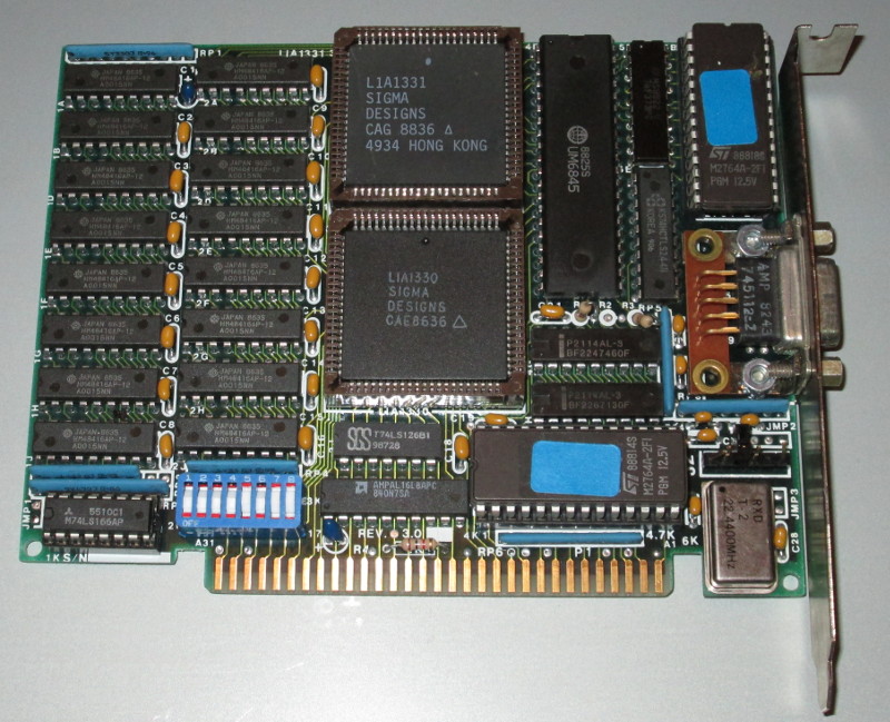
The card seems to have gone through various iterations of hardware design. Pictures of early versions show a full-length ISA card, while Total Hardware 99 shows a more compact half-length design.

According to TH99, the address ranges used by the card can be configured with DIP switches. However the BIOS in mine is hardcoded to use one specific set of addresses, so that's what I will use in the remainder of this document.
Along with the DIP switches, the card is equipped with two ROMs (one for the text-mode font, one for the BIOS), a 9-pin video connector, and a Berg connector for a light pen.
The card has two 8k ROM chips; one contains 8×8 and 8×16 fonts for text modes, while the other contains 6k of BIOS code and an 8×16 font for the 640×400 graphics mode.
| Text-mode font ROM | Graphics-mode font in BIOS |
|---|---|
 |
 |
I/O
Where a normal CGA would have its I/O ports in the 3D0-3DF range, the Color 400 uses the 2D0-2DF range. I/O accesses to 3D0-3DF can trigger a non-maskable interrupt; this is handled by the card's BIOS and translated to accesses in the 2D0-2DF range.
I/O ports are:
2D0: CRTC register select.
2D1: CRTC register value.
     The above may be replicated in the 2D2-2D7 range, but the card BIOS
     does not access these addresses.

     The X values used by the CRTC are half of what you would expect from a
     normal CGA. So the 40-column text mode has a width of 20, and 80-column
     modes have a width of 40. This means that the CRTC 'cursor address'
     registers only give the cursor position to the nearest word; bit 7 of
     port 2D9 gives the lowest bit of its address.

2D8: Mode register. The values written to this for various video modes are:
	Text      40× 25: 0xA8  1010 1000
	Text      80× 25: 0xB9  1011 1001
	Graphics 320×200: 0x0F  0000 1111
	Graphics 640×200: 0x1F  0001 1111
	Graphics 640×400: 0x7F  0111 1111
	Text      80× 50: 0x79  0111 1001
	Text      80× 30: 0xB9  1011 1001

2D9: Control register.
	Bit 7: Cursor position, low bit
	Bit 6: Unknown
	Bit 5: NMI on writes to ports 03D0h-03DFh
	Bit 3: Normally 1, set to 0 to clear lightpen latch
	Bit 2: Normally 1, set to 0 to set lightpen latch
	Bit 1:
	Bit 0: Controls what port 2DE does.
			0 => Select plane
			1 => Write to palette

	(The card BIOS seems to have an alternative mode where bits 2/3
	 are normally 0 and are set to 1 to set/clear the latch)

2DA: Status. On read:
	Bits 7-5: NMI mask / cursor position as set by last write to 2D9.
	Bit 4: Vertical retrace
	Bit 2: Light pen switch, active low
	Bit 1: Light pen trigger, active low
	Bit 0: Horizontal retrace?

     On startup, the BIOS does 100 reads of this port. If bit 1 is zero in
     all of them, it disables the NMI functionality and only emulates CGA at
     the BIOS level.

2DB: On read: Byte written to CRTC that triggered NMI.
     The BIOS writes a random value to this port after the NMI has been
     processed, presumably to clear bit 7 of port 2DC below.

2DC: On read: Bit 7 set if video adapter raised NMI.
	      Bits 00-0F give the I/O port that triggered the NMI (less
	      03D0h)
     The NMI handler writes to 2DCh at the end of the NMI handler, presumably
     to reset the NMI signal from the card to the motherboard.

2DD: Memory paging. The memory from 0xC1800 to 0xC1FFF can be either:
	* ROM: The 128 character 8×16 font for use in graphics modes
	* RAM: Use by the video BIOS to hold its settings.

	Reading port 2DD switches to ROM. Bit 7 of the value read gives the
	previous paging state: bit 7 set if ROM was paged, clear if RAM was
	paged.

	Writing port 2DD switches to RAM.

2DE: Depending on value written to port 02D9 bits 0-1, can be palette
	or plane select.

	If palette: High 4 bits = register. Low 4 bits = IRGB, active low
                    (so 0Fh is black, 0Eh is blue, ... 00h is white).
	If plane select: Write value, 0-3.

3DA: A CGA-compatible status can be read from this port. This behaviour can
     be disabled by a jumper on the card.
The BIOS does not appear to attempt to emulate the CGA 'blink' / 'bright background' toggle, so I don't know if the card supports this function.
Memory
The video RAM is arranged as four 32k planes at 0B8000h. In text modes, plane 0 contains the characters and attributes in their usual layout. The way the graphics modes work is slightly more complex.
320×200 mode
This is notionally a 4-colour mode. In fact it's a 16-colour mode, drawing its data from planes 2 and 3:
	Bits 76543210
Plane 2      ABCDEFGH
Plane 3      JKLMNPQR

There are four pixels.
Colour for pixel 0 is KBJA.
Colour for pixel 1 is MDLC.
Colour for pixel 2 is PFNE.
Colour for pixel 3 is RHQG.
When selecting the mode, the BIOS writes all ones to plane 3, and sends memory accesses to plane 2. The palette registers are programmed so that the pixel patterns map to CGA-compatible colours as they should.
640×200 mode
On a CGA, this is a monochrome mode. On the Sigma 400, it's actually a 16-colour mode; each pixel draws its colour from all four planes (bit 0 from plane 0, bit 1 from plane 1 etc.)
When the BIOS selects this mode, it clears all four planes and sends memory accesses to plane 2. Set pixels will therefore display in colour 4, so the palette is programmed to make colour 4 the foreground colour.
A program aware of the Sigma 400 can use this mode as a 16-colour mode by programming a suitable palette and accessing the plane select register.
640×400 mode
The memory layout of this mode is identical to the "AT&T" mode found on some CGA cards, or in Hercules monochrome mode:
- Lines 0,4,8,12... are at B800:0000
- Lines 1,5,9,13... are at B800:2000
- Lines 2,6,10,14... are at B800:4000
- Lines 3,7,11,15... are at B800:6000
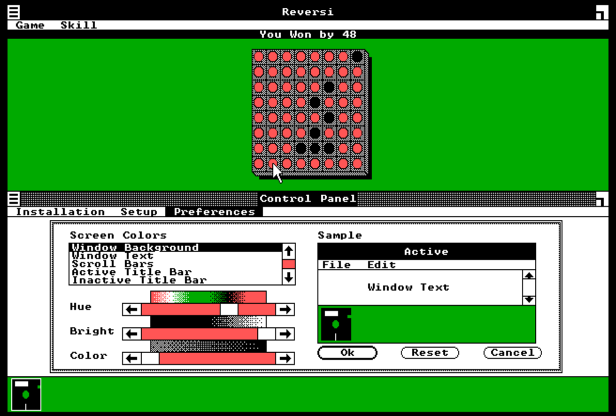
The arrangements for memory planes are identical to the 640×200 mode. By default the BIOS selects plane 1 (green) so that set pixels display in green on black. As with the 640×200 mode, full colour support is possible by programming a suitable palette and using the plane select register; this is what the Windows 1.03 drivers SIGMA4.DRV and SIGMA8.DRV do.
BIOS
The card BIOS supports the following interrupts:
INT 2 (NMI)
This checks to see whether the NMI was triggered by a write to ports 03D0-03DF; if so, it performs the appropriate translation to the card's actual video hardware.
INT 8 (timer)
This is hooked if the processor is 286 or higher. If so, it will poll the I/O channel check bit (port 61h bit 6 on ISA systems, port 62h bit 6 on PC/XT type systems) and if it's set simulate an NMI.
INT 9 (keyboard)
This resets bit 5 of port 02D9h (so the card will not trigger a NMI), calls the original INT 9 handler, and restores port 02D9h to its original value.
INT 10h (video)
The card's video BIOS provides INT 10h functions 00h-13h; some are implemented by passing the call on to the motherboard's CGA BIOS. Functions worth noting are:
INT 10h/AH=0 (set mode)
Three additional modes are supported: 40h (80×30 text), 41h (80×50 text) and 42h (640×400 graphics).
INT 10h/AH=10h (palette functions)
Subfunctions supported are 0 (set single palette register) and 2 (set all palette registers). There is no support for setting the border colour.
If the last byte of the BIOS is less than 2Fh (the same check that relates to differences in how the lightpen hardware responds to commands) then attempts to change colour 0 will be ignored.
INT 10h/AH=8Fh (installation check)
This returns:
AX = BIOS version. AH=major version, AL=minor. For example 0234h for version 2.52.
BX = video RAM segment (0B800h)
CX = video ROM segment | 80h (so 0C080h for me)
DX = I/O port base (02D0h)
INT 1Fh (graphics table):
This is expanded. Where a normal CGA BIOS would expect 1k of data for a 128-character 8×8 font, the Sigma 400 expects 3k of data: 128 8×8 characters, followed by the same characters at 8×16 resolution.
BIOS parameter table
At C000:000C is a pointer to a 5-word table:
	DW	offset mode_setups	;Table of setup data for each mode
	DW	offset mode_palettes	;Table of palette data for each mode
	DW	offset int10_funcs	;Table of INT 10h handlers
	DW	offset int9		;Address of INT 9 handler
	DW	0
The tables are:
mode_setups:
	DW	offset setup_text40	;Mode 0
	DW	offset setup_text40	;Mode 1
	DW	offset setup_text80	;Mode 2
	DW	offset setup_text80	;Mode 3
	DW	offset setup_gfx320	;Mode 4
	DW	offset setup_gfx320	;Mode 5
	DW	offset setup_gfx640	;Mode 6
	DW	offset setup_text80	;Mode 7
	DW	offset setup_mode40	;Mode 0x40
	DW	offset setup_mode41	;Mode 0x41
	DW	offset setup_mode42	;Mode 0x42

mode_palettes:
	DW	offset palette_mode0
	DW	offset palette_mode1
	...
Each mode setup table is 32 bytes long:
setup_text80:
	DB	53,40,45,4,27,12,25,26,0,15,12,15,0,0,0,0	;CRTC registers
	DB	0B9h	;0x10	Mode register 2D8
	DB	0Ch	;0x11	Control register 2D9
	DB	020h	;0x12	Character for clear screen
	DB	7	;0x13	Attribute for clear screen
	DB	3	;0x14	BIOS mode
	DW	50h	;0x15	Columns
	DW	1000h	;0x17	Buffer size
	DB	7	;0x19	Cursor end
	DB	6	;0x1A	Cursor start
	DW	03D4h	;0x1B	I/O port
	DB	29h	;0x1D	CGA mode register
	DB	30h	;0x1E	CGA colour select register
	DB	0	;0x1F	Not used
For text modes the palette table is 64 bytes, containing four sets of identical palette register values.
For 4-colour CGA mode the palette table is 128 bytes, corresponding to the possible values of the CGA mode control and colour select registers:
- Black / Red / Green / Brown
- Black / Red / Green / Yellow (high intensity)
- Black / Magenta / Cyan / Grey
- Black / Magenta / Cyan / White (high intensity)
- Black / Red / Cyan / Grey
- Black / Red / Cyan / White (high intensity)
- Black / Red / Cyan / Grey
- Black / Red / Cyan / White (high intensity)
Drivers
The Windows 1.03 driver pack (V1DSK.ZIP / V1DSK2.ZIP at textfiles.com) includes two drivers for this card: 8-colour and 4-colour. The latter is, as far as I know, the only 4-colour driver for any version of Windows 1.x:

There is another driver pack at discmaster.textfiles.com which contains the Windows drivers, plus drivers for Lotus 1-2-3 and GEM 1.x / 2.x and an image viewer.
For GEM 3.x / ViewMAX, the latest FreeGEM driver pack (version 3.14.12) contains three suitable drivers:
- SDSIG9.EGA: 640×400 in 16 colours.
- SDS2G9.EGA: 640×200 in 16 colours.
- SDCAT9.EGA: 640×400 in monochrome.
John Elliott 16 October 2018