Colour Graphics Adapter: Notes
This document describes the behaviour of IBM's original CGA, and some clones.
The CGA is a colour card. According to the IBM technical manual, it can display on one of:
- The IBM Color Display (or a compatible CGA monitor)
- A television-frequency composite monitor
- An NTSC television (with an add-on RF modulator)
The composite video output will also work with devices such as modern televisions and TV tuner cards. But if the device doesn't support NTSC, you'll only get monochrome output.
Hardware requirements
The original CGA is a full-length 8-bit ISA card. The physical shape of the card is such that it won't fit in a 16-bit slot. Cards like this are probably why many motherboards (at least up to the 486 era) had both 8-bit and 16-bit slots.
When present in a computer, the CGA uses the following system resources:
- 16k of RAM at address 0B8000h for its frame buffer. The address is incompletely decoded; the frame buffer is repeated at 0BC000h.
- I/O addresses used are 03D0h-03DFh.
The hardware
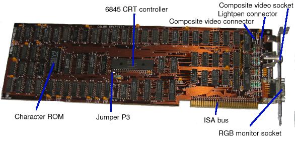
Like the MDA, the CGA is built around an MC6845 cathode ray tube controller (CRTC) and discrete logic. The two big chips are the 6845 (soldered on) and the character generator ROM (socketed). Since the character set is in ROM, the only way you'll get a different one is by replacing the ROM.
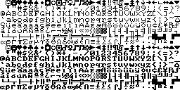
The same character ROM is used as in the MDA; so it contains the MDA's 14-row font and two 8x8 fonts (one with thick uprights and one with thin uprights). Only one of the 8x8 fonts is used at any one time; by default, it's the thick one, because the thin one doesn't show up well on composite displays.
Note that the character ROM is a 9264, which has a different pinout from the normal 27xx chip range (2764, 27128 etc.). This USENET posting describes how to get a 2764 ROM to work in a 9264 socket (it refers to the PC motherboard, but the pinout is the same for the MDA and CGA cards).
9264 pinout deduced from the above USENET post:
             +---v---+
       A7  - |01   24| - Vcc
       A6  - |02   23| - A8
       A5  - |03   22| - A9
       A4  - |04   21| - A12
       A3  - |05   20| - /OE
       A2  - |06   19| - A10
       A1  - |07   18| - A11
       A0  - |08   17| - D7
       D0  - |09   16| - D6
       D1  - |10   15| - D5
       D2  - |11   14| - D4
       GND - |12   13| - D3
             +-------+
Unlike an MDA, the CGA card does not contain a clock crystal. Instead, the Oscillator signal on the ISA bus is used to generate timing. This is 14.318MHz (4 times the NTSC subcarrier frequency). On the original PC and XT, the same clock signal, divided by 3, gave the 4.77MHz CPU clock.
On a PC with a 5161 expansion unit, the CGA should be fitted in the main PC, not the expansion unit. This is probably because the 14.318MHz clock is not shared between the PC and the expansion unit; each has its own, and they may not be in sync.
There are two external connectors - a standard RCA jack for composite video, and a DE9 socket with this pinout:
- Ground
- Ground
- Red
- Green
- Blue
- Intensity
- Reserved
- Horizontal sync
- Vertical sync
The CGA has two (or possibly three) headers on the card:
- P1 is a 4-pin header for composite video output:
- Pin 1 is +12V
- Pin 2 is not present
- Pin 3 is composite video
- Pin 4 is ground
- P2 is a 6-pin header for a light-pen:
- Pin 1 is light pen input
- Pin 2 is not present
- Pin 3 is the light pen switch input
- Pin 4 is logic ground
- Pin 5 is +5V
- Pin 6 is +12V
- P3 (next to pin 1 of the 6845 CRTC) would have a two-pin header, but is normally left as just a couple of pads. If the two pins or pads are shorted together, the alternative (thin) font is used.
The CGA uses single-ported RAM, which means that if the host PC is reading or writing screen memory, the CRT controller can't. This manifests itself as "snow" - little white rectangles (like extra cursors) briefly appear at what look like random places on the screen. Many CGA clones use dual-ported RAM and don't suffer from "snow".
Frequently-Asked Question
Since I put this page up, various people have emailed me with the following examination question:
At a particular instant a CGA monitor has the following signal applied to it:
pin 3 = 4.5V
pin 4 = 0.5V
pin 5 = 0.8V
What colour would be produced on the screen and why?
Answer:I'm not going to do your homework for you. The information already on this page should be sufficient to produce an obvious answer. To my mind, it would be obvious-but-wrong, like most of the answers on QI, but since I didn't set the question and I'm not marking the paper, my opinion on this matter isn't worth much.
Memory Maps
Text Mode
The two text modes are 40x25 and 80x25. In both, characters are 8 pixels wide and 8 pixels high. This results in either a 320x200 or 640x200 resolution.
The memory storage scheme is that two bytes of video RAM are used for each character. The first byte is the character code, and the second gives the attribute. A whole screeen is either 2000 bytes (40*25*2) or 4000 bytes (80*25*2).
Since the CGA has 16k of video RAM, several screens' worth of information can be stored in it at a time. Under most operating systems, the PC BIOS divides it into separate pages (either four or eight, depending on the video mode). DOS Plus, on the other hand, uses it to implement fast hardware scrolling (rather than move the contents of the screen "up", it moves the start of display memory "down").
Character codes match whatever the font ROM in use is. Normally this is 'codepage 437' - ASCII plus a collection of accented characters, line graphics and a few other characters.
The attributes form a bitmap:
- Bit 0: Blue foreground
- Bit 1: Green foreground
- Bit 2: Red foreground
- Bit 3: Bright foreground
- Bit 4: Blue background
- Bit 5: Green background
- Bit 6: Red background
- Bit 7: Bright background; or blinking text
(On most CGA monitors, Black+Bright shows as dark grey, and Yellow without Bright shows as brown.)
Graphics Modes
In the two graphics modes, all memory is used for the framebuffer. Each row is 80 bytes. At the beginning of memory are the first set of rows (0, 2, 4, ..., 198); offset by 8k are the second set (1, 3, 5, ..., 199). This may have been to make it easier for the hardware to produce an interlaced picture, but it's a pain to program.
In low-resolution graphics mode (320x200), a byte corresponds to four pixels; in high-resolution mode (640x200), a byte corresponds to 8. In each case, the highest-numbered bits correspond to the leftmost pixel.
Register I/O
03D8h: Mode control register
The following bits are used:
Bit 5: 1 to enable blinking, 0 to disable it.
In text modes, if bit 5 is 1, characters with attribute bit 7 set will blink. If not, they will have high intensity background. This has no effect in graphics modes.
Bit 4: High-resolution graphics
If this bit is set, it selects 2-colour graphics (640 pixels wide) rather than 4-colour (320 pixel wide). In text mode, setting this bit has the following effects:
- The border is always black.
- The characters displayed are missing columns - as if the bit pattern has been ANDed with another value. According to reenigne.org, the value is the equivalent bit pattern from the 640x200 graphics mode.
Bit 3: Enable video output
If bit 3 is 0, screen output will not be shown (it will be exactly as if the video RAM contained all zeroes). The usual use of this is if you're reprogramming the CRTC registers; disable video output beforehand and re-enable it after.
Bit 2: Black and white
If the card is displaying on a composite monitor, this disables the NTSC color(sic) burst, giving black and white output. On an RGB monitor it has no effect except in the 320x200 graphics mode, when it selects a third palette (black/red/cyan/white). This palette is not documented, and not all of IBM's later CGA-compatible cards support it.
If this bit is set to zero in 640x200 mode, you get colour composite mode.
Bit 1: Graphics mode
If this bit is set, the display RAM will be treated as bitmap graphics rather than as text.
Bit 0: High resolution
This bit should only be set in the 80-column text mode. It changes various timing parameters (to display 160 bytes per row instead of 80); the CRTC will need to be reprogrammed accordingly.
03D9h: Colour control register
The following bits are used:
Bit 5: Palette
This is only used in the 320x200 graphics mode. If it is set, the fixed colours in the palette are magenta, cyan and white. If it is reset, they are red, green and yellow. Bit 2 in the mode control register (if set) overrides this bit.
Bit 4: Bright foreground
This is only used in the 320x200 graphics mode. If set, the foreground colours display in high intensity.
Bits 3-0: Border / Background / Foreground
These 4 bits select one of the 16 CGA colours (bit 3 = Intensity, Bit 2 = Red, Bit 1 = Green, Bit 0 = Blue). In text modes, this colour is used for the border (overscan). In 320x200 graphics modes, it is used for the background and border. In 640x200 mode, it is used for the foreground colour.
Status register
This is read from port 03DAh. Its values are as follows:
- Bit 0: Display enable
- According to IBM's manual, this bit is 1 when the CPU is allowed to access video RAM without causing "snow".
- Bit 1: Light pen trigger set.
- The trigger is cleared by writing any value to port 03DBh.
- Bit 2: Light pen switch status
- This is the current state of the light pen switch - not latched or debounced. 0=on, 1=off.
- Bit 3: Vertical retrace
- Set when the screen is in a vertical retrace interval. While this bit is set, video RAM can be accessed without "snow" onscreen.
- Bits 4-7: Not used.
Lightpen registers
A write to port 03DBh will clear the lightpen latch. According to various sources, writing to port 03DCh will set the latch; this is not documented in IBM's technical manual.
BIOS-supported modes
The PC BIOS supports using a CGA in 7 modes:
| Mode number | Mode name | Mode bit 4 | Mode bit 2 | Mode bit 1 | Mode bit 0 | Notes |
|---|---|---|---|---|---|---|
| 0 | BW40 | 0 | 1 | 0 | 0 | 40x25 text. Displays in greyscale on a composite monitor, colour on an RGB monitor. Some clone BIOSes treat this the same as CO40 below. |
| 1 | CO40 | 0 | 0 | 0 | 0 | 40x25 text. Displays in colour on a composite monitor, colour on an RGB monitor. |
| 2 | BW80 | 0 | 1 | 0 | 1 | 80x25 text. Displays in greyscale on a composite monitor, colour on an RGB monitor. Some clone BIOSes treat this the same as CO80 below. |
| 3 | CO80 | 0 | 0 | 0 | 1 | 80x25 text. Displays in colour on a composite monitor, colour on an RGB monitor. |
| 4 | 0 | 0 | 1 | 0 | 320x200 graphics. Displays in colour on a composite monitor, colour on an RGB monitor. | |
| 5 | 0 | 1 | 1 | 0 | 320x200 graphics. Displays in greyscale on a composite monitor, in alternative palette on an RGB monitor. | |
| 6 | 1 | 1 | 1 | 0 | 640x200 graphics. Displays in mono on a composite monitor, colour-on-black on an RGB monitor. Some clone BIOSes don't set bit 2, resulting in colour composite mode. |
Undocumented modes
| Mode name | Mode bit 4 | Mode bit 2 | Mode bit 1 | Mode bit 0 | Notes |
|---|---|---|---|---|---|
| 160x200 | 1 | 0 | 1 | 0 | On an RGB monitor, this displays the same as the 640x200 graphics mode. On a composite monitor, this can display as a low-resolution colour mode. |
| 160x100 | 0 | 0 | 0 | 1 | This is really the 80x25 text mode. The CRTC is reprogrammed to decrease character height to two pixels, giving an 80x100 text mode. Then all character cells are filled with character 0xDE, so that the left-hand side is drawn using the background colour and the right-hand side with the foreground colour. The attribute bytes are then used to create the screen graphics. The high 4 bits of a byte give the colour of the left-hand "pixel", and the low 4 bits give the colour of the right-hand "pixel". |
160x200 composite mode
If you connect a CGA to a composite monitor, put it in 640x200 mode and turn the black-and-white mode off, you may (depending on the monitor) get a 160x200 colour graphics mode. Some CGA programs, including the Microsoft Flight Simulator, support this mode.
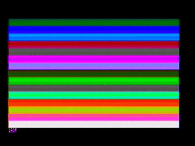
A byte roughly corresponds to two pixels, with each nibble giving the colour of one pixel. The colours visible in this mode are different from the normal CGA set; the ones I get are:
- 0: Black
- 1: Dark green
- 2: Blue
- 3: Cyan
- 4: Crimson
- 5: Dark brownish grey
- 6: Magenta
- 7: Violet
- 8: Dark grey
- 9: Bright Green
- 10: Light brownish grey
- 11: Bright Cyan
- 12: Scarlet
- 13: Yellow
- 14: Hot Pink
- 15: White
![]() composite.zip
contains additional screenshots of the CGA in the colour composite mode,
displaying the output of various test programs.
composite.zip
contains additional screenshots of the CGA in the colour composite mode,
displaying the output of various test programs.
This USENET posting also describes the 160x200 mode.
CGA Clones and Successors
The first two cards listed here are cards made by IBM; they were intended for more specialised purposes than the CGA, but emulated the CGA at a hardware level rather than providing their own video BIOSes:
3270 PC
The video controller in the 3270 PC (model 5271) contains some CGA support (enough that the XT's CGA BIOS can control it). It doesn't support high- intensity colour or 40-column modes; and support for the graphics modes is an optional extra, provided by a second full-length ISA card.
Text modes have 8 colours, with no high intensity. The screen has a 720x350 resolution; a 9x14 font is used rather than the CGA's 8x8.
Some of the CGA emulation is done by the firmware. 'Forbidden' CGA writes trigger IRQ2, and a handler then takes the proper action. The IRQ2 handler deals with cursor size and position, and mode selection.
In text modes, bits 0 (40/80 columns) and 3 (enable/disable display) of the CRT control register (port 03D8h) are ignored completely. The IRQ2 handler checks for a 40-column mode being selected, and substitutes an 80-column mode.
In graphics modes, changing any bit of port 03D8h (other than bit 1, text/graphics) causes the IRQ2 handler to clear the video RAM. Therefore it isn't possible to switch to/from the Red/Cyan/White palette without a full mode change.
The 6845 CRTC is not emulated; the undocumented 160x100 mode doesn't work. Since there is no composite output, the colour composite mode won't work either.
Professional Graphics Controller
The PGC is not just a video card; it's a miniature computer with its own processor, which communicates with the host PC through a 1k buffer. However, it can also emulate a CGA - this is necessary if it's the only video card in the system, so that the PC BIOS and non-PGC-aware programs have somewhere to send their output.
Unlike the 3270 PC, the PGC has a pretty thorough CGA emulation (a lot of it done in software running on the PGC's processor). The differences are comparatively minor:
- Text screens have a 640x400 resolution. An 8x14 font (in a 8x16 cell) is used rather than the original 8x8 one.
- On a real CGA, if bit 2 of port 03D8h and bit 5 of port 03D9h are both set, the palette used in graphics modes is red/cyan/white. On a PGC, it's magenta/cyan/white. You still get red/cyan/white if bit 5 of port 03D9h is not set. This is a firmware issue rather than hardware.
- The undocumented 160x100 mode doesn't work.
Because of the way the PGC works, most of the CGA registers and 6845 registers appear in its transfer buffer at C6000h, and can be read there by the host PC (on a standard CGA, they're nearly all write-only):
C600:03D8  CGA mode control register (port 03D8h)
C600:03D9  CGA colour control register (port 03D9h)
C600:03E0  6845 registers (14 of them) (port 03D4h/03D5h)
Sadly, while the PGC is in CGA mode, you can't reprogram its palette registers to set up custom CGA palettes.
Since there is no composite output, there are no greyscale or colour composite modes.
Plantronics ColorPlus
The Plantronics ColorPlus was an early CGA superset, which doubled the amount of video RAM to 32k (occupying B8000h-BFFFFh). The original ColorPlus was composed of two separate boards, according to this USENET posting.
The extra RAM is used as a second bit plane in graphics modes. When it is enabled, the 320x200 mode has 16 colours and the 640x200 mode has 4.
Plantronics modes are enabled by selecting a normal graphics mode and then writing to port 03DDh. Bits 4, 5 and 6 are used:
- Bit 4: 320x200 16-colour mode.
- The first plane (normally at 0B8000h) provides the red (even bits) and green (odd bits) values. The second (normally at 0BC000h) provides blue (even bits) and intensity (odd bits).
- Bit 5: 640x200 4-colour mode.
- The first plane (normally at 0B8000h) provides the red bits; the second (normally at 0BC000h) provides the green bits. As in the normal 320x200 4-colour mode, the colour select register can switch to magenta/cyan/white or red/cyan/white palettes.
- Bit 6: Swap planes
- If one of the two-plane modes is in use, this swaps the two planes over, so that the second plane appears in memory at 0B8000h and the first at 0BC000h.
If bits 4 and 5 are reset, you get normal CGA mode. If they're both set, the documentation implies 320x200 mode takes precedence.
Amstrad PC1512
The PC1512 quadruples video RAM compared to a real CGA, with 64k. In all modes other than 640x200, the extra memory is ignored. In 640x200 mode, four planes can be used to give a 16-colour display.
I have described the PC1512 CGA hardware elsewhere; salient points are:
- Most of the 6845 is not emulated, so nonstandard modes (other than the 160x100x16 mode) are unlikely to work.
- Port 03DDh controls which planes are affected by memory writes (in 640x200 mode). By default this is set to 0Fh - all planes.
- Port 03DEh controls which plane is affected by memory reads. By default this is set to 0 (blue plane).
- Port 03DFh is used to set the border colour in the 640x200 mode.
- In 640x200 mode, the low 4 bits of port 03D9h (colour select) become 'colour plane select', controlling which colour planes are visible.
- On a real CGA, if bit 2 of port 03D8h and bit 5 of port 03D9h are both set, the palette used in graphics modes is red/cyan/white. The PC1512 behaves like a PGC and displays magenta/cyan/white. You still get red/cyan/white if bit 5 of port 03D9h is not set.
The PC1512 displays only on its own monitor and has no composite output; so there are no colour or greyscale composite modes.
Amstrad PPC / PC20
The video chipset in the Amstrad PPC computers (IDA) can emulate MDA or CGA - either driving a normal TTL monitor, or the internal LCD. The desktop version (PC20 aka Sinclair PC200) has a similar system; in CGA mode it supports either a CGA monitor or a domestic television.
There is a NMI system which catches attempts to reprogram the CGA and hands them over to the BIOS. This is so that programs which try to change mode manually by altering CRTC registers still work despite the different CRTC values used by an LCD or television. On the PPCs, the NMI system is also used to detect attempts to set up the 160x100 mode.
The LCD is a 2-colour device, so the colour CGA display has to be adjusted to display on it. Text modes compare the intensity of the foreground and background colours, and invert the character if the background is brighter. If the foreground is high intensity, the character glyph will be 'eroded' and appear thinner. The standard graphics modes all behave as 640x200 monochrome.
The television output behaves like a fuzzier version of an RGB monitor; there are no special composite modes.
For full details, see the technical manual. In brief, the following I/O ports behave differently:
- 03D8h
- This port is read/write on the PPC/PC20. Attempts to write to
this port may trigger the video NMI.
- Bit 4: (Monitor) If this is set in text modes, all characters are drawn with a black background.
- Bit 6: (LCD) Select 160x100 mode.
- Bit 7: (LCD) Display characters with non-black backgrounds in inverse video.
- 03DDh
- If the video chipset raised an NMI, this port says why:
- Bits 0-4: Last selected CRTC register.
- Bit 5: Set if NMI was caused by write to the CRTC.
- Bit 6: Set if NMI was caused by write to port 03DEh.
- Bit 7: Set if NMI was caused by write to port 03D8h.
- 03DEh
- This port controls the extra features of the PPC / PC20. It is
a read/write port; a read returns the last value written (except
for bits 3-5, which return the state of the video DIP switches).
Attempts to write to this port may trigger the video NMI.
- Bit 0: 1 for external video, 0 for LCD (PPC) or TV (PC20).
- Bit 1: 1 for MDA mode, 0 for CGA mode.
- Bit 2: 1 to disable built-in video chipset, 0 to enable.
- Bits 3-5: Read state of configuration switches 1-3.
- Bit 6: 1 to allow writes to CRTC registers 0-11, port 03D8h and this port. 0 to ban writes.
- Bit 7: 1 to raise an NMI if a prohibited port is accessed, 0 not to.
- 03DFh
- If the video chipset raised an NMI because of a write to the CRTC, this port gives the value that was written.
Olivetti M24 (also sold as AT&T 6300, Logabax 1600)
This computer's built-in display hardware (IDC) is similar to CGA, but it has twice as much video RAM and an extra 640x400 graphics mode (mode 40h). According to the technical documentation, there's also a 512x256 mode which can only be used by the optional Z8000 coprocessor. Text modes use an 8x16 font rather than 8x8.
A "Display Enhancement Board" (DEB) can also be fitted; this gives 640x400x16 colours and adds lightpen support.
Other unusual physical features of the M24 display controller are:
- Rather than the display controller plugging into the ISA bus, it incorporates two ISA sockets. The motherboard and the backplane for other ISA cards plug into the controller. If you want to replace the video card with something better, you need a substitute card with the two sockets (but no video hardware).
- The monitor socket is DB-25 rather than DE-9.
I/O ports differ as follows:
- Addresses are incompletely decoded, so ports 03C0h-03CFh are the same as 03D0h-03DFh. This means an EGA or VGA can't coexist with the IDC.
- The light pen ports, and ports 03DDh and 03DFh have no effect unless a DEB is present.
- Port 03DAh returns a monitor ID in bits 4-5 (2=colour, 3=mono; other values reserved). If a DEB is present, bits 6 and 7 will be 0; otherwise they will be 1.
- Port 03DEh controls the extra features:
- Bit 0: Set for 640x400 or Z8000-compatible modes.
- Bit 1: Set to degauss the monitor (colour monitor)
- Bit 2: Set to select alternate character set (if an 8k character ROM is fitted).
- Bit 3: If not in 640x400 mode, select whether the first or second 16k of video RAM is being used.
- Bit 4: Set to 0 for 640x400 mode, 1 for 512x256 mode.
- Bit 5: Not used.
- Bit 6: Underline characters with a blue foreground.
- Bit 7: Use pixel clock from Z8000 board. If the Z8000 board is not present, the IDC will 'shut down'.
In the 640x400 mode, the display has four sets of rows rather than two. The first set (rows 0, 4, 8, 16, ..., 396) are at 0B8000h; the second (rows 1, 5, 9, 17, ..., 397) are at 0BA000h; the third (rows 2, 6, 10...) are at 0BC000h; and the fourth at 0BE000h.
There is no composite output, and hence no composite mono or colour modes.
Later Olivetti computers (at least up to the PCS series) support mode 40h even when the remainder of their display hardware is more conventional. The same mode is also present on some Compaq portables, and (under different numbers) the Toshiba 3100 and DEC VAXmate.
Olivetti Prodest PC1
The PC1 is an all-in-one XT-compatible computer. Its built-in display hardware emulates CGA. Output is possible to an RGB monitor (my PC1 won't display a stable picture on an IBM CGA monitor, so it may require an EGA monitor); to a composite monitor; or to a SCART television.
Like the PC1512, the PC1 does not have a full CRTC; the first 10 registers are simply ignored by the BIOS. A write to port 03D8h is sufficient to do a mode change.
There appears to be additional video hardware at ports 03DDh (address) and 03DEh (data). At startup, the BIOS writes 106 bytes of data to these addresses.
The PC1 font ROM appears to contain a second character set which could be used to display Teletext. Whether this set can be selected by software (perhaps using ports 03DDh/03DEh) I don't know.
The BIOS allows mode 40h to be selected, but this comes out as 640x200 rather than 640x400.
Compaq Portable / Deskpro
The CGA card in these computers is capable of displaying a 24x80 text mode at MDA resolution (720x350, with 9x14 pixel characters). This is set up by the BIOS, which programs the 6845 registers slightly differently from normal. One of the changes it makes is to set the character height to 14, and this triggers the support circuitry on the card to switch to the MDA pixel clock and 9x14 font.
Later models of the card have the additional ability to use MDA attributes (high-intensity, blink and underline) in the high-resolution 24x80 mode. This is selected by setting bit 7 in port 03D8h.
Tecmar Graphics Master
This card can emulate either an MDA or a CGA, as well as providing its own high-resolution graphics modes. It can be installed on its own, alongside an MDA or CGA, or as a third card in a machine with both.
Online sources are not always clear about how the jumpers on the card should be set. Here's my interpretation:
| Configuration | Switch SW1 | JP7 | JP1/A | JP1/B | JP1/C | JP1/D | JP1/E | JP1/F |
|---|---|---|---|---|---|---|---|---|
| Graphics Master is primary display emulating CGA | Down | Open | Closed | Closed | Closed | Open | Open | Open |
| Graphics Master is primary display emulating MDA | Up | Closed | Closed | Closed | Closed | Open | Open | Open |
| Graphics Master is secondary display emulating CGA (primary is MDA) | Down | Open | Closed | Open | Closed | Open | Open | Open |
| Graphics Master is secondary display emulating MDA (primary is CGA) | Up | Closed | Open | Closed | Closed | Open | Open | Open |
| Graphics Master is tertiary display using CGA monitor | Down | Closed | Open | Open | Closed | Open | Open | Open |
| Graphics Master is tertiary display using MDA monitor | Up | Closed | Open | Open | Closed | Open | Open | Open |
The card's extra video modes appear to be selected by a second control register at 03DAh.
John Elliott 18 October 2017