Plantronics ColorPlus: Notes
The Plantronics ColorPlus is one of the first attempts at a CGA-compatible video card with additional functionality. In this case, the extra functionality is a doubled colour depth in graphics modes. That is, where a normal CGA can do 320×200 in 4 colours or 640×200 in 2, a ColorPlus can do 320×200 in 16 colours and 640×200 in 4.
System requirements
The ColorPlus will plug into an 8-bit or 16-bit ISA slot. It uses the following system resources:
- 32k of RAM at address 0B8000h for the frame buffer.
- I/O addresses 03D0h-03DFh.
Hardware
Physically, the ColorPlus is composed of two full-length ISA cards. The bottom card has the video output connector, plus CGA-compatible connectors for composite video and the light pen. The top card contains the font ROM (a 2732 chip with 4k of memory), five jumpers, and a printer port.
![[Plantronics card, dismantled]](Images/plantronics.jpg)
Like the CGA, the ColorPlus has no clock crystal; it relies on the Oscillator signal from the ISA bus.
There are two external connectors - a DB25 parallel printer port, and a and a DE9 socket with the same pinout as CGA:
- Ground
- Ground
- Red
- Green
- Blue
- Intensity
- Reserved
- Horizontal sync
- Vertical sync
The two headers on the back of the card are:
- A 4-pin header for composite video output:
- Pin 1 is +12V
- Pin 2 is not present
- Pin 3 is composite video
- Pin 4 is ground
- A 6-pin header for a light-pen:
- Pin 1 is light pen input
- Pin 2 is not present
- Pin 3 is the light pen switch input
- Pin 4 is logic ground
- Pin 5 is +5V
- Pin 6 is +12V
Jumpers
The jumpers behave as follows:
- WJ1
Printer port base address. If the jumper is fitted, 0x378 (LPT2). If not, 0x278 (LPT1).
- WJ2 / WJ3
If the font ROM is a 2732, putting a jumper on WJ2 will disable it, and moving the jumper to WJ3 will enable it. This isn't particularly useful.
If, however, the font ROM were to be replaced with a 9264 (like the font ROMs on the original IBM CGA and MDA) then this jumper would combine with WJ4 / WJ5 below to select one of four fonts in the ROM.
On my card, neither WJ2 nor WJ3 have jumper pins; instead, a wire is permanently soldered across WJ3.
2732 and 9264 pinouts (9264 deduced from a USENET post, not verified):
2732 9264 +---v---+ +---v---+ A7 - |01 24| - Vcc A7 - |01 24| - Vcc A6 - |02 23| - A8 A6 - |02 23| - A8 A5 - |03 22| - A9 A5 - |03 22| - A9 A4 - |04 21| - A11 A4 - |04 21| - A12 A3 - |05 20| - /CE, Vpp A3 - |05 20| - /OE A2 - |06 19| - A10 A2 - |06 19| - A10 A1 - |07 18| - /OE A1 - |07 18| - A11 A0 - |08 17| - D7 A0 - |08 17| - D7 D0 - |09 16| - D6 D0 - |09 16| - D6 D1 - |10 15| - D5 D1 - |10 15| - D5 D2 - |11 14| - D4 D2 - |11 14| - D4 GND - |12 13| - D3 GND - |12 13| - D3 +-------+ +-------+- WJ4 / WJ5
- Font select: controls the A11 pin on the font ROM (or the A12 pin if it's a 9264). Putting the jumper on WJ4 will pull the line high (thick font); putting it on WJ5 will pull it low (thin font).
There are also jumpers, or positions for them, on the back card. The behaviour of these is pure guesswork from following PCB traces; on the card I have, they are all hardwired to 'jumper present' and I haven't experimented with changing any of them.
- WJ1
- Unknown.
- WJ2
- I/O base address. If jumper present, 03D0h. If jumper absent, 01D0h.
- WJ3
- Memory base address. If jumper present, 0B800h. If jumper absent, 0A800h.
In use
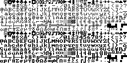
At system startup, the card behaves like a normal CGA. It also supports two extra video modes using the full 32k of video RAM: 320×200 in 16 colours or 640×200 mode in 4 colours. The font displayed is very similar to the original IBM:
The extra graphics modes are selected by switching to a normal graphics mode, and then writing to port 03DDh. Bits 4, 5 and 6 are used:
- Bit 4: 320×200 16-colour mode.
- The first plane (normally at 0B8000h) provides the red (even bits) and green (odd bits) values. The second (normally at 0BC000h) provides blue (even bits) and intensity (odd bits).
- Bit 5: 640×200 4-colour mode.
- The first plane (normally at 0B8000h) provides the red bits; the second (normally at 0BC000h) provides the green bits. As in the normal 320×200 4-colour mode, the colour select register can switch to magenta/cyan/white or red/cyan/white palettes.
- Bit 6: Swap planes
- If one of the two-plane modes is in use, this swaps the two planes over, so that the second plane appears at 0B8000h and the first at 0BC000h.
If bits 4 and 5 are reset, you get normal CGA mode. If they're both set, 320×200 mode takes precedence.
Software support
The extra video modes were not widely supported, but some pieces of software did / do make use of them:
- CompuShow supports the 320×200 16-colour mode.
- GEM drivers are available for the 640×200 4-colour video mode.
Compatible systems
Although the extra video modes were not widely used, they were implemented by a few CGA-compatible video cards:
- The Paradise EGA 480 chipset (when set to emulate CGA rather EGA). This is the chipset used in the Amstrad PC1640.
- The ATI Graphics Solution (aka the "Small Wonder").
- According to Total Hardware 99, the Tandy 250-3045, 250-3045A and 250-3048 graphics cards supported the extra modes. It is possible that these were based on the same ATI or Paradise chipsets.
John Elliott 28 March 2015